Coordinate systems
Contents
Subject Coordinate System (SCS / CTF)
Brainstorm uses the CTF coordinate sytem. All the surfaces, sensors and additional points are converted into this system when they are imported in Brainstorm.
It is defined in the following way:
Based on: Nasion, left pre-auricular point (LPA), and right pre-auricular point (RPA).
Origin: Midway on the line joining LPA and RPA
Axis X: From the origin towards the Nasion (exactly through)
Axis Y: From the origin towards LPA in the plane defined by (NAS,LPA,RPA), and orthogonal to X axis
Axiz Z: From the origin towards the top of the head
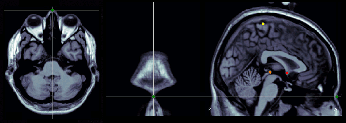
Nasion (NAS)
The nasion is the intersection of the frontal and two nasal bones of the human skull. Its manifestation on the visible surface of the face is a distinctly depressed area directly between the eyes, just superior to the bridge of the nose (source: Wikipedia).
Use the coronal orientation to define it.
Pre-auricular points (LPA, RPA)
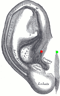
The proper definition of the preauricular point is: "a point of the posterior root of the zygomatic arch lying immediately in front of the upper end of the tragus". This is illustrated with the green point below. The problem with this definition is that it can be really difficult to localize precisely on the MRI. It can lead to severe misregistration between MRI and MEG/EEG. More information on the anatomical location of this point on the FieldTrip website.
Our proposition is to use instead the junction between the tragus and the helix, marked with a red dot in the following figure. It can be located much more precisely both anatomically and on the MRI slices.
Use the sagittal orientation to define it.
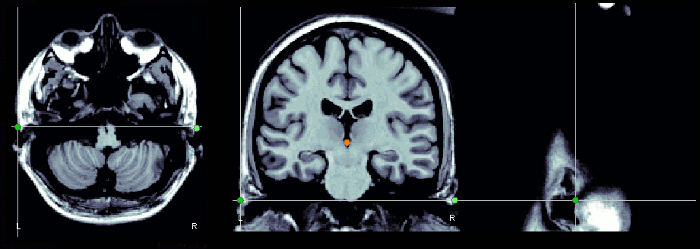
You can choose to use this definition of the "preauricular point" or not. The most important is to use the same convention for all the steps: digitization of head points with a magnetic system (Isotrak Polhemus, ...), and analysis with Brainstorm.
Notes for CTF users
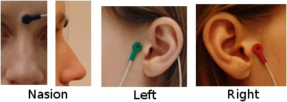
Using a CTF system, you would probably prefer to use the head localization coils to indicate these NAS/LPA/RPA points, instead of these "anatomically correct" points. The coordinate system in the CTF files is based on the position of the three coils you stick on the head of the subject. Typically, the nose coil is slightly above the nasion, and the ear coils about one centimeter more frontal than the points that were previously described.
A good practice is to take pictures of the subject with the coils on, right before bringing him/her in the MEG, and digitize the position of the center of the coils as the nasion/LPA/RPA. Then, when importing the MRI in Brainstorm, try marking as accurately as possible the position of the coils in the MRI. You cannot be very precise at this point, but the errors here are fixed later with the automatic registration.
IMPORTANT: These comments do not apply if you use the Brainstorm Digitize program to drive the Polhemus device. In this case, you are asked to digitize two sets of NAS/LPA/RPA points: the coils and the real anatomical points. Just make a copy of the .pos file saved by Digitize in the .ds folder, then set the real anatomical points in the MRI. Brainstorm is going to automatically handle the transformation between the CTF coils coordinate system and the real subject coordinate system. The result is usually much more accurate and does not require to take pictures of the subjects.
Using a default anatomy
The fiducial points (Nasion, LPA, RPA) used in your recordings might not be the same as the ones used in the anatomy templates in Brainstorm (Colin27, ICBM152, FSAverage). By default, the LPA/RPA points are defined at the junction between the tragus and the helix, as represented with the red dot.
If you want to use an anatomy template but you are using a different convention when digitizing the position of these points, you have to modify the default positions of the template with the MRI Viewer.
- Go to the anatomy view
In (default anatomy), right-click on the MRI > Edit MRI
- Modify the position of the fiducial points to match your own convention
- Click on [Save], it will update the surfaces to match the new coordinate system
MNI coordinates
Two types of normalized coordinates are widely used in the literature: the atlas defined by Jean Talairach, and the MNI stereotaxic coordinates. You can read about the differences between these two systems on that page: http://imaging.mrc-cbu.cam.ac.uk/imaging/MniTalairach
Two of the templates distributed with Brainstorm (Colin27 and ICBM152) are registered in the MNI stereotaxic space, therefore the "MNI coordinates" can be derived easily from the MRI voxel coordinates. For these two brains, you can read the normalized MNI coordinates directly in the interface ("MRI Viewer" or "Get coordinates" menu). The values should be almost identical to what you get when opening these volumes with the "Display" program from the MINC tools.
To be able to get "MNI coordinates" for individual brains, an extra step of normalization is required.
The method we use in Brainstorm is based on an affine co-registration with the MNI ICBM152 template from the SPM software. This function directly uses code from SPM12 (spm_maff8 ©J Ashburner), described in the following article: Ashburner J, Friston KJ, Unified segmentation, NeuroImage 2005
To compute the linear transformation matrix between the individual MRI and the ICBM152 template:
- In the MRI Viewer: Click on the link "Click here to compute MNI transformation".
In the database explorer: Right-click on the MRI > Compute MNI transformation.
Talairach coordinates
If we cannot compute the MNI transformation as presented in the previous section, we use an approximation to the Talaraich coordinate system. It relies on two points, the posterior and anterior commissure, and the midsagittal plane. The third point needed here, the interhemispheric point, is used to define this plane. You can read about the differences between these two systems on that page:
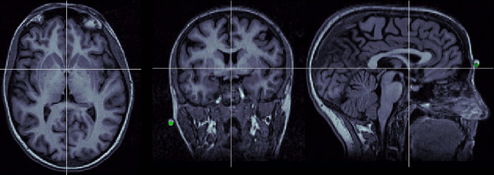
Anterior commissure (AC)
Description of the anterior commissure at this Wikipedia page.
Technique to localize it:
- Use the axial orientation.
- Start from a slice just below the corpus callosum and move around it (slightly up or down)
- You are looking for a small fiber tract that connects the two hemispheres
- You should find two spots corresponding to this description. The more frontal one is the anterior commissure, the other one is the posterior commissure
- Once you have localized it: if it is visible on more than one slice, use the upper one (the one closest to the top of the head).
Posterior commissure (PC)
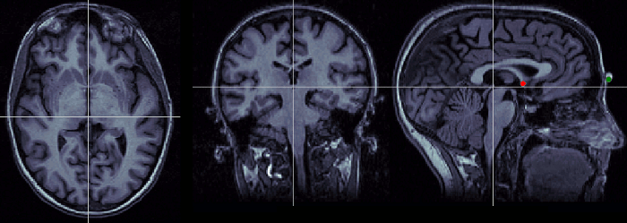
Description of the posterior commissure at this Wikipedia page.
Technique to localize it:
- Use the axial orientation
- It is a fiber tract similar to the anterior commissure, but a few centimeters more posterior.
- If it is visible on more than one slice, pick the lowest one.
Interhemispheric point (IH)
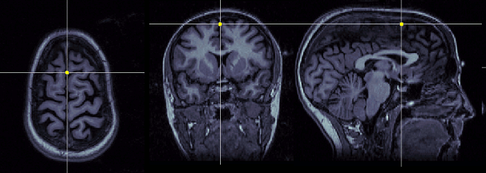
Pick any point in the interhemispheric space, somewhere in the top of the head. Do not use a point too close from the commissures.
Neuromag coordinates
This coordinates system is not used in Brainstorm, and described here only FYI. All the information contained in Neuromag .FIF files are in this CS, and converted to Brainstorm SCS at importation.
It is defined in the following way:
Based on: Nasion, left pre-auricular point (LPA), and right pre-auricular point (RPA).
Origin: Intersection of the line L through LPA and RPA and a plane orthogonal to L and passing through the nasion.
Axis X: From the origin towards the RPA point (exactly through)
Axis Y: From the origin towards the nasion (exactly through)
Axiz Z: From the origin towards the top of the head
MRI coordinates
Coordinates system used to index voxels in the space of the MRI volume, in millimeters:
Axis X: left>right
Axis Y: posterior>anterior
Axis Z: bottom>top
- Coordinates of the first voxel at the bottom-left-posterior of the MRI volume: (1,1,1)
Converting between coordinate systems
The conversions between coordinate systems is handled with one single function cs_convert:
sMri: MRI structure from the database: right-click on the MRI file > File > Export to Matlab > sMri
- src/dest: Source and destination coordinates systems: {'voxel', 'mri', 'scs', 'mni'}
- P: List of points [Npoints x 3]
All the the coordinates have to be in meters (not millimeters).
Pdest = cs_convert(sMri, 'src', 'dest', Psrc);
Examples:
P_mri = cs_convert(sMri, 'voxel', 'mri', P_voxel);   % Voxel => MRI coordinates
P_mni = cs_convert(sMri, 'scs', 'mni', P_scs);       % SCS   => MNI coordinates
Additional discussion on the forum
http://neuroimage.usc.edu/forums/showthread.php?1429-Bad-MEG-MRI-coregistration
http://neuroimage.usc.edu/forums/showthread.php?1389-Co-registration