Digitize EEG sensor locations and head shape
Authors: Elizabeth Bock, Marc Lalancette
Contents
This page describes the Digitize GUI for the updated version 2024.
For the legacy (previous) version, visit:
https://neuroimage.usc.edu/brainstorm/Tutorials/TutDigitizeLegacy
Getting Started
The Brainstorm Digitize application allows for a connection to a Polhemus device and collection of digitized head points and/or EEG sensor locations.
The application is designed for two receivers (i.e. the stylus and reference) and one transmitter.
The connection to the device is made via a serial port connection. This can be accomplished using a direct serial connection or with a USB-to-Serial cable connection with the USB side connecting to the host computer.
Configuration of the Polhemus
Fastrak or Isotrak
- These devices operate at 9600 baud, 8 bits, no parity
Configure the unit using the switches at the back of the device: 11001001
(9600 baud, 8 bits, parity:none, rs232)- Configure the computer's COM port for the same
Select fastrak for Unit Type in the GUI settings (see below)
Patriot
- This device operates at 115200 baud, 8 bits, no parity
- Configure the unit using the switches at the back of the device (all down)
- Configure the computer's COM port for the same
Select patriot for Unit Type in the GUI settings (see below)
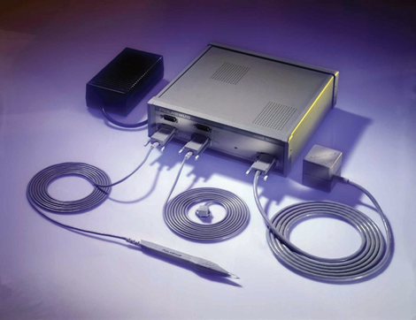
Figure 1. Polhemus system with two receivers and one transmitter
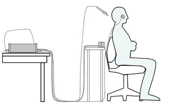
Figure 2. Typical Polhemus setup
The application is designed for two receivers (i.e. the stylus and reference) and one transmitter.
The stylus is used by the operator to point to the desired position for collection
The reference is fixed to the subject’s head, typically with glasses or headband. While the subject’s head can move during the collection, the reference sensor should not move from the starting position relative to the head. Take special care in how the receiver is attached as any slight movement with respect to the head will be amplified in the point coordinates and may lead to bad coregistration. It is best to ask the subject not to move during the entire procedure, and to restart if you accidentally hit the receiver.
The transmitter is fixed behind the subject, typically to a non-metal chair or table. The orientation is shown here, with X+ pointing up and Y+ point to the right.
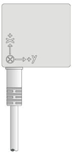
Figure 3. Transmitter orientation
****Care should be taken when setting up this system to ensure accurate collection. Thorough testing should be performed using known head coordinates (phantom) to determine accuracy.
The head coordinate system used in the Digitize application is based on the CTF head coordinate system, see CoordinateSystems.
The Digitize GUI
Before starting the GUI, turn on the Polhemus unit and wait until the indicator light is green.
To start the Digitize application, start Brainstorm. Then select ‘Digitize’ from the File Menu.
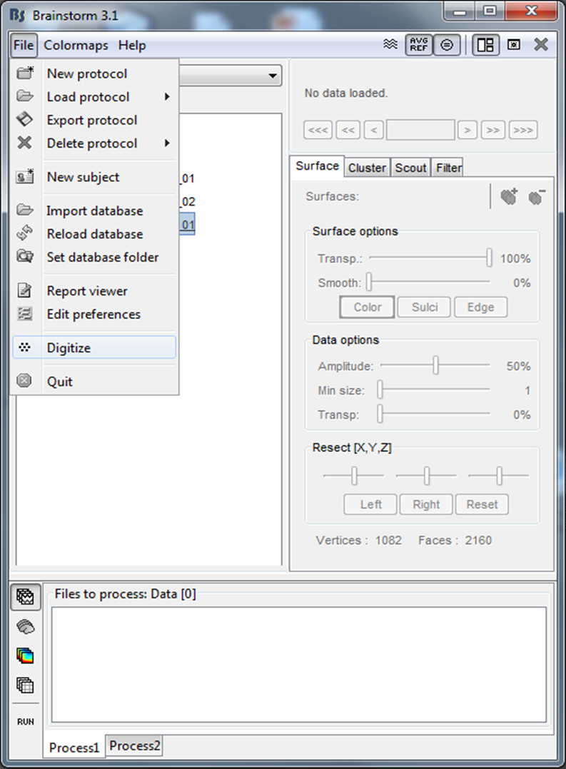
Figure 4. Starting Digitize
The Brainstorm GUI will be hidden during the use of the Digitize application and will reappear after exiting Digitize.
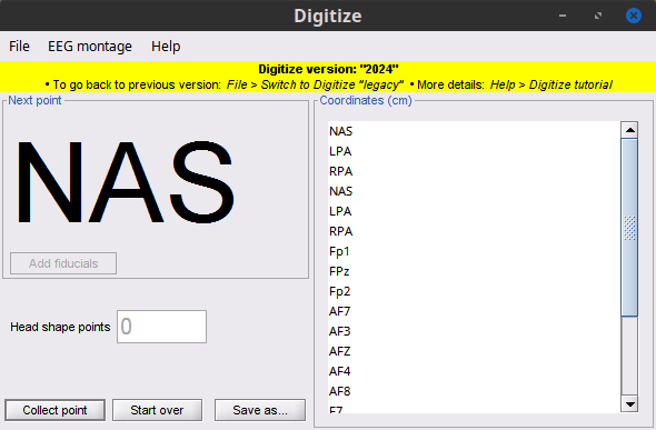
Figure 5. Digitize GUI
This application allows you to collect:
- Three anatomical landmarks for MEG/MRI co-registration (NAS, LPA, RPA)
- Up to four head localization coils (HPI) for computing the head coordinate system
- EEG sensor locations
- Scalp points for head shape
The collection can performed by:
- One operator who will press the button on the stylus to collect a point
- Two operators, where one will point the stylus at the desired location and one will click the ‘Collect Point’ button on the lower panel of the GUI.
Points are collected in order defined in the Settings, see next section.
If an error is made during collection:
- The last point can be removed by clicking “Delete Last Point” on the lower panel of the GUI (after all HPI points are collected only - otherwise restart)
- The entire session can be restarted by selecting ‘Start Over’ from the File menu
When complete the coordinates can be save in a variety of formats including CTF (*.pos), megDraw (*.eeg) or tab-delimited ASCII text.
Edit Settings
Settings for the serial connection and point collection can be adjusted using the ‘Edit settings’ menu option from 'File' menu in the Digitize GUI.
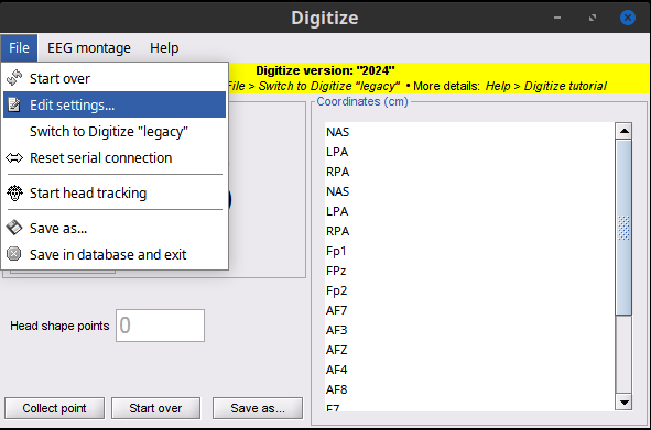
Figure 6. Edit Settings
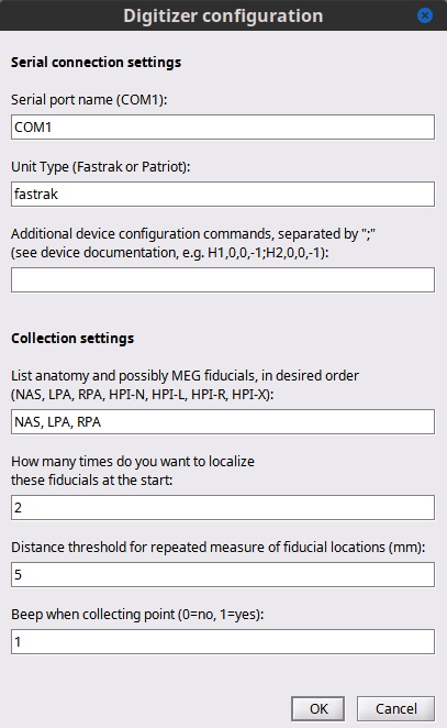
Figure 7. Edit settings dialog
Serial connection settings
Serial port name – this is the name of the serial port that is connected to the Polhemus, for example COM1 (Windows), ttyS1 (Linux).
Unit Name – this will select the settings for the specific device. Fastrak and Isotrak will both use the name fastrak.
Additional device configuration –
TODO: PROVIDE MORE INFO ON PARAMETERS OR RELEVANT LINKS
Collection settings
List of anatomy and possible MEG fiducials - this will allow to customize the order of acquisition for the anatomy fiducials and the HPI coils. This is important for CTF users since the data collected from the MEG system is saved in HPI coil coordinate system (
TODO: IS THIS STILL CORRECT ???
). Users collecting only EEG sensors or just head shape will not collect these points.
Number of times to collect the above-listed fiducials – these collections will occur at the beginning of the session and will be averaged together to compute the transformation to the HPI or head coordinate system.
Beep – this will generate a beep sound with each point collection (this is often helpful to realize a button press on the stylus when there is one operator).
EEG Montages
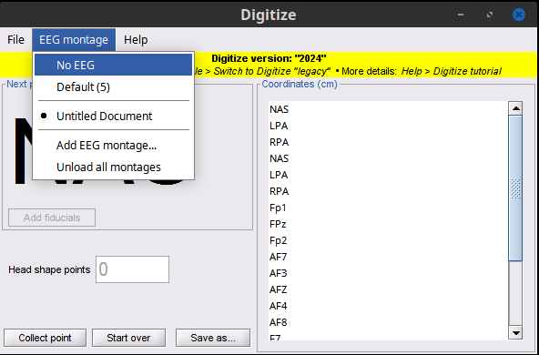
Figure 8. Edit EEG settings
There are three options for EEG sensors:
- No EGG: No collection and therefore no labels
- Default: This is entered as a number and the default labels are used: EEG01, EEG02, EEG03, etc.
- Add EEG montage: A custom number of points is collected and the specified labels are used. This should be defined in a tab delimited plain text file as shown.
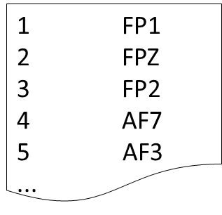
- Figure 9. Example EEG montage
EEG settings should be adjusted for each session. Custom montages that are imported are stored in the brainstorm preferences and are available on subsequent sessions.
The Coordinates list on the left panel of the GUI displays the labels of the points which have been selected for collection. This is vary depending on the number of times the fiducials are collected and the number of EEG sensors to be defined. The head shape points are not listed since this will vary depending on the individual need.
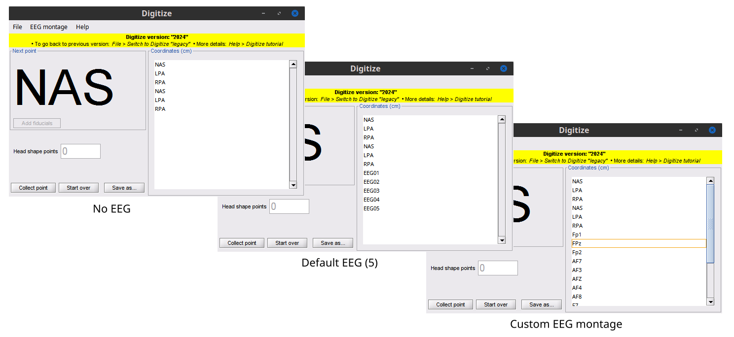
Figure 10. Example EEG setups
Collection
Collection of anatomy fiducials and possible MEG fiducials is performed following the order indicated in the Settings.
Collect the required number of Anatomical Fiducials
When collecting more than one set of fiducials, an error message is displayed if the difference between the sets is > 5mm
- If the MEG HPI coils are not used, then the head coordinate system is computed with the anatomical fiducials and the points are plotted on the 3D point display. Unless the user changes the anatomy for the brainstorm Digitize subject, the default anatomy is used. It may not match exactly the subject being digitized, but should be a good quality control image to ensure the points are positioned where expected.
- Note that the 3D figure is a standard Brainstorm window, where you can use all the mouse operations (rotation, zoom, popup menu) and the keyboard shortcuts (predefined view, screen capture...) introduced in the previous tutorials.
- The coordinates are displayed in the coordinate list in cm
- The points are saved in the brainstorm channel file as CARDINAL Head Points
- The collection automatically moves to EEG (if desired) or head shape
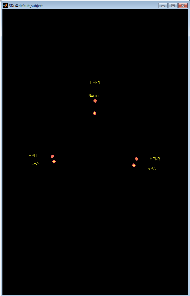
Figure 11. Collect fiducials
Collect the required number of HPI coils
When collecting more than one set of fiducials, an error message is displayed if the difference between the sets is > 5mm
- Once collected, the head coordinate system is computed and the points are plotted on the 3D point display overlayed on the scalp surface. Unless the user changes the anatomy for the brainstorm Digitize subject, the default anatomy is used. It may not match exactly the subject being digitized, but should be a good quality control image to ensure the points are positioned where expected.
- Note that the 3D figure is a standard Brainstorm window, where you can use all the mouse operations (rotation, zoom, popup menu) and the keyboard shortcuts (predefined view, screen capture...) introduced in the previous tutorials.
- The coordinates are displayed in the coordinate list in cm
- The points are saved in the brainstorm channel file as HPI Head Points
- The collection automatically moves to Anatomical Fiducials
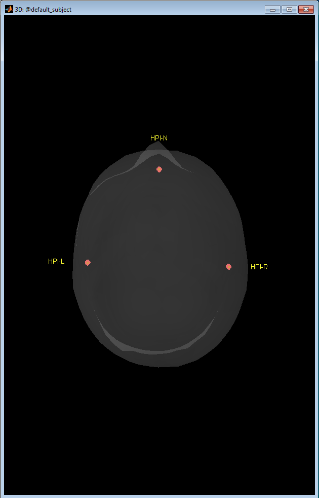
Figure 12. Collect coils
Collect the required number of EEG points
- Each point is displayed on the 3D points display
- The counter is incremented each time a point is collected and therefore indicates which point needs to be collected next
- The coordinates are displayed in the coordinate list in cm The points are saved in the brainstorm channel file as both EEG Channel Locations and EEG Head Points
- Once complete, the collection automatically moves to the head shape collection
Collect the desired number of head shape points
- In order to take full advantage of the MEG/MRI co-registration algorithms in Brainstorm, it is recommended to collect approximately 100-150 points from the head: 5-10 points from the boney part of the nose, 10-15 points across the eyebrows, then an even coverage of the scalp from the eyebrows to the inion. It is NOT recommended to collect points below the inion on the neck, since the shape of the neck can change between lying in the MRI scanner and sitting during point collection. Even coverage is more important that dense coverage. See Figure 13 as an example.
- Each point is displayed on the 3D points display
- The counter is incremented each time a point is collected and therefore indicates which point will to be collected next
- The coordinates are displayed in the coordinate list in cm
- The points are saved in the brainstorm channel file as EXTRA Head Points
- Once complete, the operator can save the points to a text file in a variety of formats.
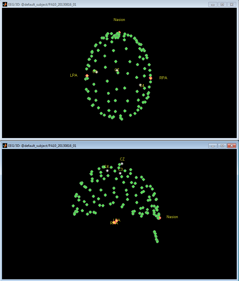
Figure 13. Collect head shape
Save
- The points can be saved as a POS file for import into CTF datasets or your Brainstorm database. Select 'Save as...' and confirm the file name and location.
When exiting the program, select File > Save and Exit to ensure the points are saved in the Brainstorm database.
Export points to text file
All points are automatically saved in a Brainstorm channel file
- After exiting from the Digitize application, the points can be written to a text file in a variety of formats.
Right click on the channel file just created, select File > Export to file, select the type of file to save.
Figure 14. Export points to text file
How to use this file with CTF systems
The procedure we recommend is the following:
- Export the file in the format "EEG+headshape: Polhemus (*.ds)"
- Copy the .pos file to all the CTF datasets recorder for this subject (.ds folder)
- When importing the CTF datasets in Brainstorm, the file will be automatically loaded.
Troubleshooting
TODO: THIS SECTION MAY NEED TO BE UPDATED TO THE NEWER GUI (VERSION 2024)
There are several things that can affect the quality and reproducibility of the measurements from the Polhemus Fastrak:
Hardware problems
The hardware is fragile. Dropping the stylus, receiver or emitter once can break them in a way that gives bad localization but seems to work otherwise. Reading the error codes from the built in tests (BIT), e.g. with Polhemus' PiMgr software, is a quick way to verify the hardware. Polhemus support can help you with this, and give you the password to download and install PiMgr. Note that PiMgr will not work over a 9800 baud serial connection. It's easier to use the USB connection instead for this, but remember to disconnect the USB cable from the Polhemus and restart it before trying again with Brainstorm over a serial cable.
Device communication
Problem appears to be with the communication between the device and Brainstorm:
- Power on the device
- Restart Matlab
- Start brainstorm
- Start Digitize
- At the Matlab command prompt, type this: s = instrfind()
If you do not have Matlab, you can open a command prompt from the Brainstorm File menu BEFORE starting Digitize. The command, s = instrfind() should be typed into the window, click execute and see the output in the terminal window.:
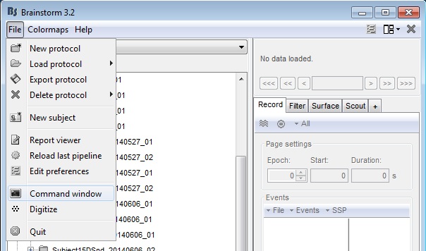
Figure 15: Start command window from Brainstorm
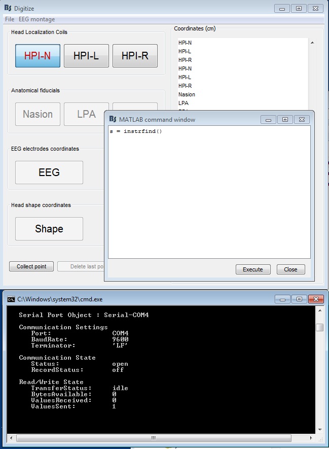
Figure 16: Serial connection settings (Fastrak)
From the Digitize->File->Edit settings (Figure 7), confirm the information in 's' matches your settings
- Confirm the information in 's' matches your COM port settings of your computer (this info is in the Device Manager)
- Press the button of the stylus, then execute s = instrfind() again. You should see that there are bytes available (94 bytes for Fastrak, 120 bytes for Patriot).
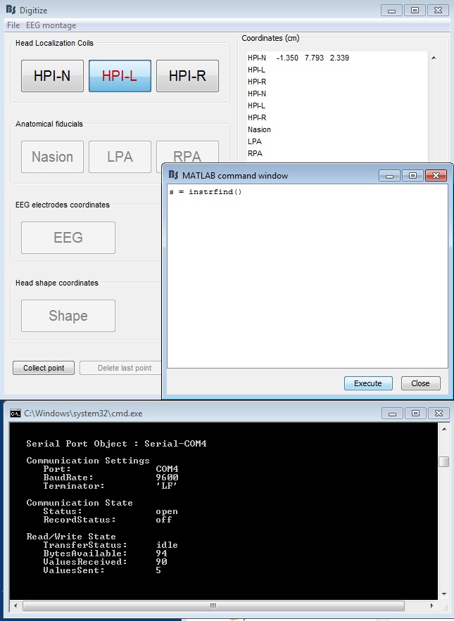
Figure 17: Serial connection after one point collected (Fastrak)
Accuracy
Be very careful not to move the mounted receiver during collection (or between collections when comparing the two). This is crucial and difficult to achieve to the level needed for good coregistration. To help with this, the person should be told not to move their head during the procedure.
- It is very sensitive to its environment: magnetic distortions by nearby metal objects (e.g. chair or shielded room) or electromagnetic interference (computers). Ideally, this should be performed in the middle of an open space on a plastic or wooden chair. We recommend doing many tests, moving the setup around the room, to find the best spot where the errors between measurements are a minimum. You could do this directly with Matlab to collect points so that you skip the Brainstorm step which transforms the anatomical points to headspace.
The placement of the transmitter and receivers should match the device configuration, which specifies which half-sphere around the emitter is measured, and the accepted angles and distances from the emitter. Note that PiMgr is buggy and might not work for correctly setting these configuration parameters. We recommend doing it through the serial interface. Refer to the Polhemus manual for a full list of commands and configuration, but some are listed below. Once a working configuration is found, you could save these commands in your panel_digitize.m file, in the CreateSerialConnection function, so that you don't have to worry about them being reset or changed outside Brainstorm. (We might add some functionality to simplify this in the future, as this trick might have to be repeated when updating Brainstorm.)
Example configuration commands:
  % Open connection
    fopen(SerialConnection);
    if strcmp(DigitizeOptions.UnitType,'fastrak')
      %'c' - Disable Continuous Printing
      % Required for some configuration options.
      fprintf(SerialConnection,'c');
      %'u' - Metric Conversion Units (set units to cm)
      fprintf(SerialConnection,'u');
      %'F' - Enable ASCII Output Format
      fprintf(SerialConnection,'F');
      %'R' - Reset Alignment Reference Frame
      fprintf(SerialConnection,'R1');
      fprintf(SerialConnection,'R2');
      %'A' - Alignment Reference Frame
      %'H' - Hemisphere of Operation
      fprintf(SerialConnection,'H1,0,0,-1'); % -Z hemisphere
      fprintf(SerialConnection,'H2,0,0,-1'); % -Z hemisphere
      %'l' - Active Station State
      % Could check here if 1 and 2 are active.
      %'N' - Define Tip Offsets % Always factory default on power-up.
      %    fprintf(SerialConnection,'N1'); data = fscanf(SerialConnection)
      %    data = '21N  6.344  0.013  0.059
      %'O' - Output Data List
      fprintf(SerialConnection,'O1,2,4,1'); % default precision: position, Euler angles, CRL
      fprintf(SerialConnection,'O2,2,4,1'); % default precision: position, Euler angles, CRLF
      %fprintf(SerialConnection,'O1,52,54,51'); % extended precision: position, Euler angles, CRLF
      %fprintf(SerialConnection,'O2,52,54,51'); % extended precision: position, Euler angles, CRLF
      %'Q' - Angular Operational Envelope
      fprintf(SerialConnection,'Q1,180,90,180,-180,-90,-180');
      fprintf(SerialConnection,'Q2,180,90,180,-180,-90,-180');
      %'V' - Position Operational Envelope
      % Could use to warn if too far.
      fprintf(SerialConnection,'V1,100,100,100,-100,-100,-100');
      fprintf(SerialConnection,'V2,100,100,100,-100,-100,-100');
      %'x' - Position Filter Parameters
      % The macro setting used here also applies to attitude filtering.
      % 1=none, 2=low, 3=medium (default), 4=high
      fprintf(SerialConnection,'x3');

      %'e' - Define Stylus Button Function
      fprintf(SerialConnection,'e1,1'); % Point mode

      %'^K' - *Save Operational Configuration
      % 'ctrl+K' = char(11)
      %'^Y' - *Reinitialize System
% 'ctrl+Y' = char(25)- We previously recommended that the orientation of the stylus should always be perpendicular to the scalp surface. However, while this may reduce variability between repeated measurements, it could increase bias instead which is a bigger issue, or hide a problem with the stylus which is calibrated and should not depend on its orientation. We now recommend varying the orientation of the stylus to avoid bias and to run tests and contact Polhemus support if there seems to be increased variability in repeated measurements with different orientations.
Additional documentation
Forum: Stylus orientation issues
Forum: Emitter position
Forum: Stylus button not working (some info about the PiMgr app with screenshots)
