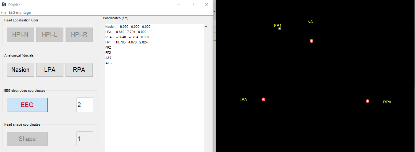
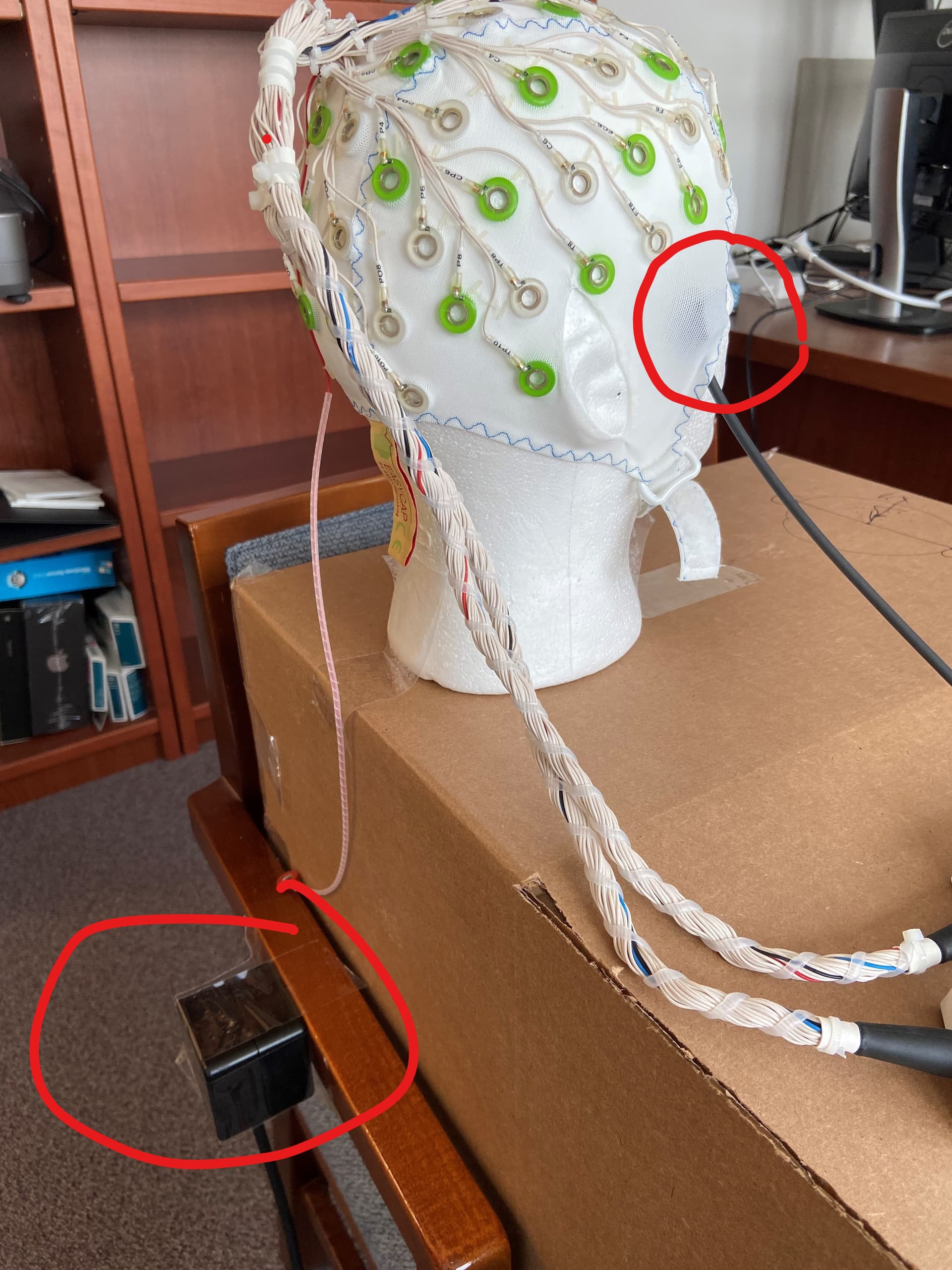
Hello! I am aiming to digitize all of the electrode locations on our EEG cap. It appears that I have accurately digitized the anatomical fiducial positions, however, when I go to collect an EEG electrode location that is at the very top of the head, the location appears to be to the left of the Nasion, which is inaccurate (see image). Our physical set-up is also pictured. We've tried several different testing locations and receiver orientations without success. Any ideas on why the location of the EEG electrode is so far off and what we can do to resolve the issue?
Hello,
One thing to consider is the configuration of the Polhemus. It is designed to only capture locations in half a sphere next to the emitter (e.g. positive Z direction). If the relative placement and orientation of the emitter does not match the configuration, you may get strange results. You can also check for errors (e.g. due to defective parts) in the Polhemus PiMgr app for example, but that's unlikely if the fiducials digitize well.
I updated this part of Brainstorm slightly recently in our lab to set some of these configuration parameters during initialization, but I haven't pushed it yet. I could have a look at it next week.
Marc
Thanks for the response Marc. When you say "configuration", do you mean some configuration in Brainstorm that needs to be specified to match the physical placement and orientation of our emitter? I followed the "Digitize EEG sensor locations and head shape" tutorial exactly - are you saying that there is some additional configuration parameters (beyond the tutorial) that need to be done in the software? If you could provide some specific guidance about adjusting the Brainstorm configuration, that would be much appreciated.
Hi,
Sorry, no I mean the configuration of the Polhemus device itself, which is not currently completely done in Brainstorm. It's not too clear, but at the very end of the tutorial it says:
As for the orientation of the transmitter, this may be trial and error depending on the settings of your device.
Again, the digitizer is designed to measure only one hemisphere around the emitter: the receivers should always be located in that same hemisphere. Which hemisphere is set either via commands through the serial port, or with PiMgr for example. You should refer to the device manual.
As an example, here's what I added in our local Brainstorm to avoid settings changing unexpectedly (as happened to me once):
%'c' - Disable Continuous Printing
% Required for some configuration options.
fprintf(SerialConnection,'c');
%'u' - Metric Conversion Units (set units to cm)
fprintf(SerialConnection,'u');
%'F' - Enable ASCII Output Format
fprintf(SerialConnection,'F');
%'R' - Reset Alignment Reference Frame
fprintf(SerialConnection,'R1');
fprintf(SerialConnection,'R2');
%'H' - Hemisphere of Operation
fprintf(SerialConnection,'H1,0,0,-1'); % -Z hemisphere
fprintf(SerialConnection,'H2,0,0,-1'); % -Z hemisphere
%'O' - Output Data List
fprintf(SerialConnection,'O1,2,4,1'); % default precision: position, Euler angles, CRLF
fprintf(SerialConnection,'O2,2,4,1'); % default precision: position, Euler angles, CRLF
%'Q' - Angular Operational Envelope
fprintf(SerialConnection,'Q1,180,90,180,-180,-90,-180');
fprintf(SerialConnection,'Q2,180,90,180,-180,-90,-180');
%'V' - Position Operational Envelope
% Could use to warn if too far.
fprintf(SerialConnection,'V1,100,100,100,-100,-100,-100');
fprintf(SerialConnection,'V2,100,100,100,-100,-100,-100');
%'x' - Position Filter Parameters
% The macro setting used here also applies to attitude filtering.
% 1=none, 2=low, 3=medium (default), 4=high
fprintf(SerialConnection,'x3');
%'e' - Define Stylus Button Function
fprintf(SerialConnection,'e1,1'); % Point mode
Cheers
Marc