Hello,
This post is about something I have been thinking about on and off since I started learning about MEG, but never formally written. I am finally taking the courage to ask about it.
TLDR: Why, when doing distributed source imaging, with dipole constrained to the cortical surface, are the dipoles placed at the vertex of the cortical mesh and not in the center of each face of the cortical mesh?
Long story:
When doing distributed source imaging, we place dipoles along the cortical surface. Each dipole represents an equivalent patch of cortex with the corresponding cortical column. In the cortex, because the neurons are aligned, this forms an equivalent dipole that is perpendicular to the cortical surface. Now, we describe the cortex as a triangular mesh (a set of vertices and faces). Currently, we place the dipole at each vertex. But I was wondering if we should not, instead, have one vertex per face.
Here are some reasons why I think it would make sense :
Visualization:
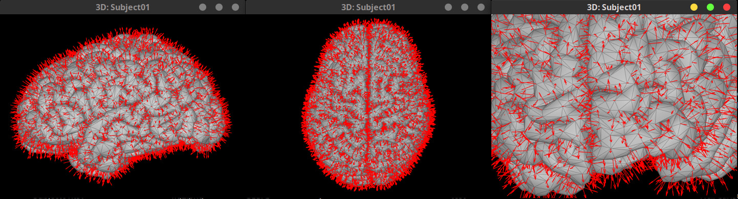
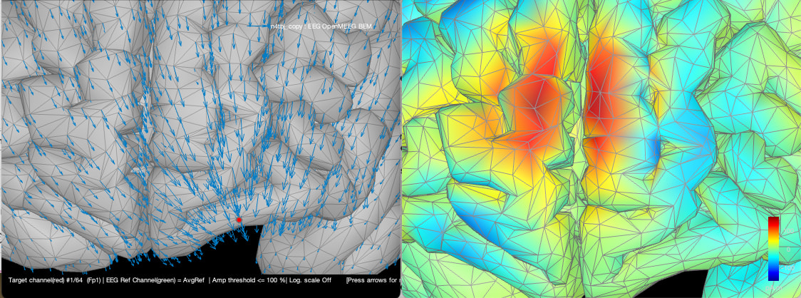
When inspecting the head model, we see that there is one dipole per vertex (left – although they don’t appear to be normal to the cortical surface). But when we visualize the result, we dont actually display the dipole’s intensity at each vertex, but smooth the result to color the faces of the mesh (right).
We can see this effect when we apply a threshold and create a scout based on the activated patch:
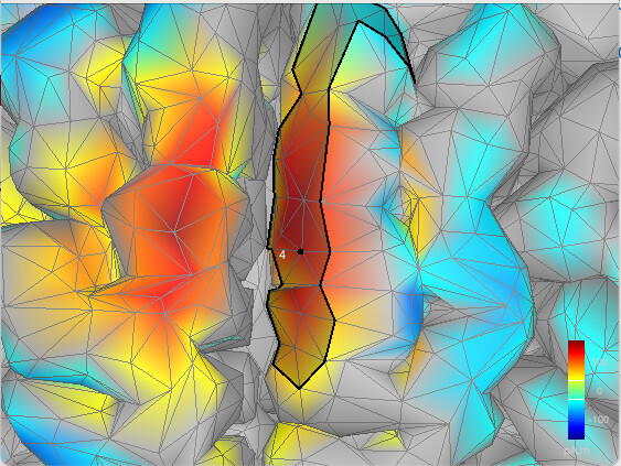
The activation seems to be larger than the scout. This is minor, but I think I saw multiple questions on the forum asking why Scout seemed to leave empty patches. Notably, here, if we define a second scout for the negative activity. It would seem that a hole would exist between the two scouts (since there is no vertex there).
Putting the dipole at the center of each face would solve the issue since we could then color each face and eventually allow the user to control the amount of spatial smoothing applied. Additionally, defining scout as a set of faces would solve the issue of where to put the boundaries.
Defining the normal vector
When we do ESI/MSI, we often constrain the vector to be normal to the surface. If we consider a face, then defining the normal to that face is easy. But i dont know how to define the normal to a single point when we put the dipoles at the vertex location.
Interpretation:
Each dipole is supposed to represent a volume of cortex. (equivalent area * cortical thickness). However, defining the area covered by each vertex is not evident. (I know brainstorm can give an estimate from tess_area). But to me, it’s not obvious what the equivalent area of cortex is associated with each dipole.
I think this is important as (unless I am mistaken), the activity found after source localization is directly proportional to the area of cortex corresponding to each dipole. If we have 5 dipoles, each with an amplitude A, then modeling them with 1 equivalent dipole would result in an amplitude of 5A. The thing I am not sure about is why the unit after source localization is pA.m when I always thought it should be pA.m^2. Since we have a current over a specific area.
If we place one dipole per face, then it’s direct to see what portion of the cortex is modelled by each dipole (the corresponding triangle), and we can easily associate an area of cortex with each dipole. This means that we can then display the current map (pA.m2) –> meaning that larger triangles will have a bias towards larger amplitudes, but also a normalized map pA where we normalize the amplitude of each dipole using the area of cortex covered by the dipole.
My hypothesis is that doing so would help reduce the impact of the mesh inhomogeneity (e.g., there is variability in the size of each face). In fMRI, people have found that having an homogenous mesh could help reduce some bias when estimating functional connectivity ( A cortical surface template for human neuroscience - PMC )
Conclusion:
From a code perspective i guess there shouldn’t be too much difference from putting the dipole at the mesh edge vs at the center of each triangle. But I guess there is a reason I am missing that leads to that choice? Or was it considered, but both methods are actually leading to the same results?
Thanks for reading 
Feel free to let me know if anything is unclear haha