Dear Francois & team,
I would need to find the MNI coordinates corresponding to the following locations of the 10-20 system: P3, P4, F3 and F4.
I installed the latest version of Brainstorm but could not find a way to do this. Would you be able to help me obtain these 4 sets of coordinates?
Thanks very much!
Best wishes,
Tudor
Hi Tudor,
You get them by doing the following:
- Create a new subject, using the default anatomy
- Create a condition, right-click on it > Use default EEG cap > Colin27 > 10-20 (19)
- Right-click on the channel file > Export to Matlab > ChannelMat
- Right-click on the MRI file > File > Export to Matlab > sMri
- Electrodes locations of channel #i in SCS:
xyz_scs = ChannelMat.Channel(i).Loc’;
- Convert to MRI coordinates (millimeters):
xyz_mri = cs_scs2mri(sMri, xyz_scs’ .* 1000)’;
- Convert to MNI coordinates (meters):
xyz_mni = cs_mri2mni(sMri, xyz_mri’)’ ./ 1000;
Those coordinates systems are documented:
http://neuroimage.usc.edu/brainstorm/CoordinateSystems
Cheers,
Francois
Hi Francois,
Many thanks for your reply. Really sorry but I could not quite follow those instructions. I did not find an option to create a new [I]condition[/I], only a new [I]protocol[/I], and if I do that, then step 3 and onwards don’t seem to match, e.g. I don’t have a ‘channel’ or an ‘MRI’ entry to right-click on.
You mention above commands from converting from “SCS” and “MRI” coordinates to MNI, however I only need a 10/20 to MNI conversion. I was not really any clearer on this after reading the documentation you linked to.
The easiest thing would be if I could find those values already tabled, since I’d be surprised if I were the first to wonder what the MNI coordinates corresponding to the rather limited number of 10-20 locations is. However, I am wondering what space I should be asking Brainstorm to give me those coordinates in - is it the standard MNI space, each individual subject’s space, or perhaps it is acceptable to use the subject-specific template (the T1 representing an average of all subjects)? Although more accurate anatomically, I would prefer to use the same set of MNI coordinates for all subjects.
Thanks again!
MNI coordinates of the points you requested, in millimters, on the default Colin27 brain in Brainstorm:
P3 (channel #8 ): -53 -87 44
P4 (channel #7): 56 -86 44
F3 (channel #4): -58 35 50
F4 (channel #3): 59 36 50
The MNI coordinates are available only for MRI volumes standardized to the MNI stereotaxic space. In Brainstorm, this will be most likely the case only of the templates Colin27 and ICBM152.
Please read and follow carefully all the introduction tutorials (12+3) before trying to use Brainstorm by yourself.
Then read the tutorials #1, #3 and #4 in the “Anatomy” section.
Please come back to me if you have questions that are not answered by those tutorials.
Thank you very much Francois!
One more question. A paper that has used 10-20 locations transformed to MNI coordinates is this: http://www.jneurosci.org/content/31/43/15284.short
One of their electrodes was positioned on F3, and they report the MNI coordinates x=-34, y=26, z=44. Unfortunately, they did not also use F4, P3, P4.
I know these are many approximations involved in such a conversion, but the x coordinate in particular seems quite different from that which you mentioned, i.e. theirs is a remarkable 24mm more medial.
Any idea what might be the source of this large difference for the x, and which of the two sets of coordinates is likely to be more accurate?
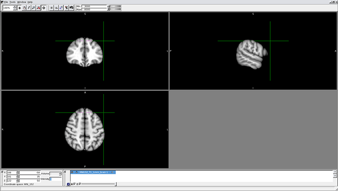
I entered the coordinates you indicated into an MRI viewer (FSLview), having loaded an MNI template, but the point in space corresponding to each of the 4 sets of coordinate is always well outside of the brain (screenshot shows location of the putative F3 point).
Is it possible these are in fact not the right MNI coordinates? Otherwise, am I doing something wrong?
Thanks again.
Hi Tudor,
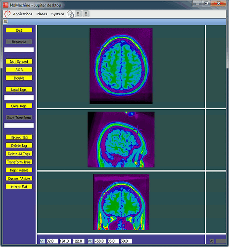
I double-checked what the MINC tools were giving for the positions I gave you: they are all touching the skin. See example below (F3).
I cannot tell you how or why you get wrong displays with other programs.
In general, we advise people not to work with standardized coordinates. The "MNI coordinates" don't make much sense for individual MRIs, and most programs use them quite randomly. They are coordinates in the MNI stereotaxic space, they can be used only for volumes that have been normalized using the MINC tools.
The positions I have set for the 10-20 system in the Brainstorm default EEG caps are not accurate. I just placed them manually on the MNI Colin27 head surface. I did my best, but I would not be surprised to observe 2cm differences with a different setup (different heads, different EEG caps). Trying to be accurate when you are working with a standard brain (which is probably a lot bigger than your subject's head) and with a standard EEG cap (where the electrodes never end up where they are supposed to be) is somewhat pointless.
Cheers,
Francois
Thanks Francois - I see what you mean. I guess the reason why the coordinates appear outside of the brain is that they are meant to correspond tot he scalp (not underlying brain) location of the 10-20 coordinate. Would it make sense, then, to take as my cortex-level coordinate for e.g. F3 the projection (perpendicular to the cortex) starting from the F3 scalp coordinates that you indicated? And would it make sense to just make this coordinate change visually, i.e. by clicking on the MNI template brain point that seems the closest (by Euclidian distance) to the original point?
I realise the approximate nature of such a transformation (and of the scalp coordinates themselves), but there is probably not much more that can be done to increase spatial accuracy, as you say.
Why would you do this?
I don’t think you should be trying to link one electrode a brain location at all.
If you want to link the sensors to the brain, calculate a forward and an inverse model.
Francois
Others have done that before, though (linking electrode positions to brain locations):
-
Santarnecchi et al., Current Biology 2013:
[I]“Stimulating electrodes were positioned according to the International 10–20 EEG System: the ‘‘active’’ electrode was centered on the left middle frontal gyrus (x = –34, y = 16, z = 30)”[/I]
-
Keeser et al., J Neurosci 2011:
[I]"The areas below the tDCS electrodes were defined as regions of interest (ROIs) using EEG positions F3 (anode) and Fp2 (cathode) of the 10–20 electrode system. Conversions from these coordinates to MNI coordinates were drawn from the center of the stimulation electrodes (MNI coordinates for F3: x=-34, y=26, z=44) according to the 10–20 electrode system on the closest MNI cortical standard space using the Muenster T2T-Converter and then converted to a binary form. The electrode ROIs were positioned for each subject separately with a cube width of 35 mm horizontal (anode) or vertical (cathode) using MANGO (Multi-Image Analysis GUI). Areas outside the cortex were rejected individually. Masks of the RSNs and the theoretically chosen area below the anode and the cathode electrodes were created for each subject and all four conditions separately. "[/I]
Ok, if this is for placing stimulating electrodes, it makes more sense. But unfortunately I have no experience with this.
I suggest you contact the authors of those articles directly if you have questions on their methodology.
Francois
I already did, only one replied, and suggested that I use Brainstorm to obtain the coordinates 
Haha! Well, I guess I have to come up with some smarter ideas to help you then…
One thing you could try to “project the electrodes on the cortex” would be the following:
- Copy the cortex surface (CTRL+C/CTRL+V)
- Set it as the default SCALP surface (Right-click > Set surface type)
- Right-click on the channel file > MRI registration > Use the button [Project electrodes on scalp]. It should do some sort of orthogonal projection of the electrodes on the cortex surface…
I haven’t tested it, but you could try
Francois
Thanks very much Francois! I am very tight on time unfortunately, and completely unexperienced with Brainstorm, so I’ll try to see if I can do this some other way, and if not I’ll come back to Brainstorm and try my luck following your instructions.
Hey Francois,
I tried to get coordinates for the orthogonal projection starting from the scalp coordinates, but didn’t get far following your steps. In case it doesn’t take you too long, do you reckon you might do me the favour of projecting those for me and posting the coordinates - or perhaps make the instructions more rookie-friendly? 
Many thanks indeed!
T
Hello,
Sorry for the response delay, I was away until today.
Can you tell me precisely at what step your are blocked?
Thanks,
Francois
Hi Francois. I wasn’t really sure what your instructions referred to from the 1st step tbh, and because as I said I just haven’t used BS before and I was pressed for time, I have instead in the meantime started a different approach, with a collaborator. I’ll know in a few days whether it leads to useful results. In case it is quick for you to obtain those cortical level coordinates for the 4 regions, it would still be useful to have them, although right now my concern is related not to much to the centre coordinates but to exactly what shape and size the ROI should have. I’ll be creating the ROIs in FSL, where all masks are created cubical.
thanks again
I won’t be able to help you here because I’m not sure I understand what you are trying to do.
The only thing I can do is helping you finding your way through the software, but you’d have to produce your results by yourself.
Let me know if you need my help later.
Francois


