Hi, all.
I am trying to convert surface files to .obj files to show the models. And since there are no texture files, so
I tried to add color values using the weight files (the idea is very simple,
check the value of the vertex in the weight file If it is above 30 then set 0 0 1 else set 0.8 0.8 0.8) inside the .obj files, the format is shown in below.
eg: the first 3 numbers are the x,y,z, and the remaining numbers for RGB values.
v -2.276386 -3.295356 64.484711 0 0 1
v 20.158056 -80.026299 54.145271 0.8 0.8 0.8
v 39.799774 12.014405 47.524158 0.8 0.8 0.8
v 7.921703 102.537949 11.302989 0 0 1
However, the color is shown in the model, but the order is not correct. In the beginning, I thought it was because the order of the vertex is changed when the surface files are converted to .obj file.
However after I tried 4 different ways to convert it, it did not show the correct result. I tried importing the weight files into the brainstorm as the texture map and it works, so I assume the vertex's order inside the weight file is correct. If anyone has any possible solution for me please help.
solution1:
online tools use stl to convert obj
result: not match
solution2:
python convert stl to obj
result: not match
solution3 (This way did not change any order it should be correct but the result is not):
use freesurfer to convert
mris_convert inflated_avg inflated_avg.asc
mv inflated_avg.asc inflated_avg.srf
use script srf2obj
gawk -f srf2obj inflated_avg.srf > inflated_avg.obj
result: not match
solution4:
use blender to convert stl to obj, mtl file will be generated too but useless
result: not match
The surface files are the general surface files used in freesurfer, In the above link I have shared one sample. It can also be imported into the Brainstorm.
The weight file is FreeSurfer weight file format and contains one value per listed vertex. I assume the order of the vertex value is the same as in the surface file, otherwise, it should not match after I use it as texture in brainstorm. I also shared a sample in the cloud link.
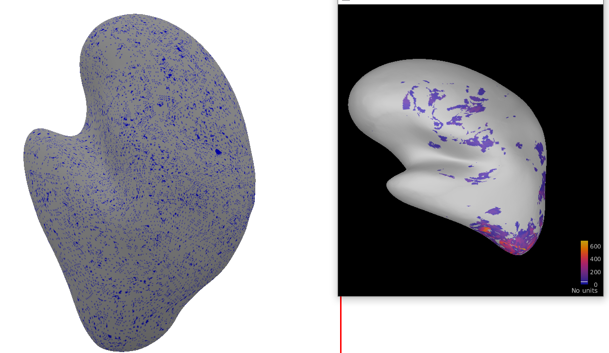
The model refers to the left side, the obj file can be used in other 3D model viewer tools, but the color on this surface is not the same as the right side.
Sorry for making you confused. I will list the steps of what I am trying to do. Original surface file: lh.inflated_avg Orignal weight file: En_Ph_R1-vreg+orig_f-lh.w
Step 1: I use a surface file(from freesurfer) and convert it to .stl and then convert to .obj file which is a model file for another 3D model viewer such as Blender... (The .obj file already can be used right now, but it does not contain any color)
Step 2: I use a weight file and convert it to a .txt file (let's call it weight.txt) which contain a list of vertex value. At this moment, I thought the order or the vertex value in weight.txt had the same order as the vertex in the *.obj (In the .obj file, you can add an RGB value after the vertex coordinates. The format is shown in the questions). Therefore, I simply add the RGB value for each line of the .obj by checking the value in the weight.txt if it is bigger than 35 then set 0 0 1, else then set 0.8 0.8 0.8. In this step I use objEditor.py to do it and generate a small_colored_lh.obj file. But the result is not the same as in Brainstorm.
Here is the updated: The result is correct now, It seems like the script I used to convert the weight file to weight.txt has wrong order of the vertex value, after I used Brainstorm to see the content of the weight file and exported it to use in the objEditor, it works now.