Hello everyone,
I have a problem setting the electrodes in 2 subjects of my study correctly.
The resliced MRI/CT after doing an SPM reslicing of a pre surgery MRI(t1-mprage) with a post surgery CT seems to look quite well. But when it comes to setting of the electrodes it doesn´t work out in 2 of my 32 subjects.
After setting tip and skull entry correctly as well as the parameters of the implanted electrodes (worked in the other 30 subjects and more than 150 electrodes), the virtual electrode is not computed correctly. The space in between the single contacts is to small so that the last contact does not fit to the actual skull entry.
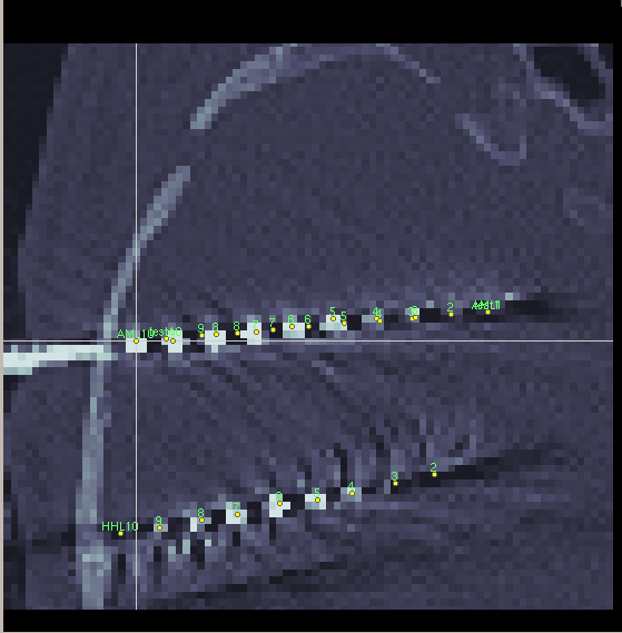
In this picture you can see such a virtual electrode laying over the actual electrode you can see in the CT.
Any help and comments are appreciated!
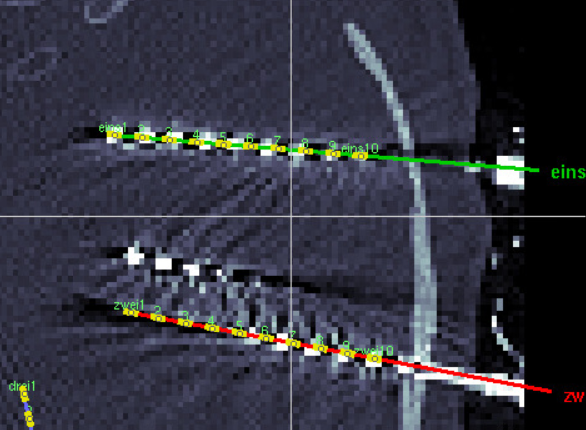
I guess you are talking about the red electrode?
It is difficult to see what is happening here, as we don't see the beginning of the electrode.
If you are confident that there are no issues in the positioning of the electrode (tip of the electrode, number of contacts and contact spacing are correct), two other reasons can explain misalignment of the last contacts between the Brainstorm model (yellow dots, coordinates saved in the channel file) and the CT:
- The CT is slightly distorted, due to subjects movements or other artifacts. As the SPM-based registration done in Brainstorm is a rigid registration (no deformation allowed between the CT and the T1 MRI), such distortions can't be compensated. This might be difficult to observe when overlaying the T1 and the CT if the distortion is as little as a few millimeters. Running a non-rigid registration outside of Brainstorm (with SPM or other tools) might help with this.
- The electrode is bent: the leads are flexible, and sometimes end up being really curved. This case can't be handled automatically in Brainstorm, where all SEEG electrodes are assumed to be perfectly straight. This would however cause the last yellow do to be farther out than the actual contact in the CT, so it is probably not your problem.
Consider these yellow dots as a default position that you are allow to fix manually.
If you feel that the misalignment of a contact is sufficient to cause problems in your analysis, click on the dot and drag it to the center of the CT hypersignal using the three slices of the MRI viewer.
Keep in mind that you will probably use the T1 MRI as the reference for your analysis, not the CT, therefore in case of distortions between the CT and the MRI, the priority is to have the contacts positioned correctly on the MRI.
Hi Francois,
unfortunately the problem ist not that easy....
Of course, we can move the yellow electrode dots, but I'm afraid that somehow the scale is not correct anymore in those two subjects.
In the screenshot, you see the manually moved electrode AML with 10 contacts and the new implanted electrode test with 10 contacts and the correct electrode settings and it is not matching at all. It seems shifted by at least one contact.
Do you have any other helpful ideas about this issue?
Thanks and best, Johannes
It is difficult to understand what is going on not knowing what you did and not having the data in hand to test it.
The logic of the automatic positioning of the contact is simple: you set the tip of the electrode (this is contact #1), then any other point along the electrode, to give a direction. The electrode information (contact number and spacing) is used to position the electrodes along this axis.
If there is no scaling issue (correct voxel size and no CT distortion) and the electrodes are not bent, then the problem has to be either the positioning of the first contact or the distance between 2 contacts (value "Contact spacing", which must be set before setting the tip and skull entry points)
Am I missing something?