|
Size: 6426
Comment:
|
Size: 16360
Comment:
|
| Deletions are marked like this. | Additions are marked like this. |
| Line 2: | Line 2: |
| This page describes the various coordinate systems used in Brainstorm, and explains how to convert beetween referentials. <<TableOfContents(2,2)>> |
|
| Line 3: | Line 7: |
| Brainstorm uses the CTF coordinate sytem. All the surfaces, sensors and additional points are converted into this system when they are imported in Brainstorm. | Brainstorm uses the CTF head coordinate system. All the surfaces, sensors and additional points are converted into this system when they are imported in Brainstorm. |
| Line 8: | Line 12: |
| * __Origin__: Midway on the line joining LPA and RPA * __Axis X__: From the origin towards the Nasion (exactly throught) * __Axis Y__: From the origin towards LPA in the plane defined by (NAS,LPA,RPA), and orthogonal to X axis * __Axiz Z__: From the origin towards the top of the head |
* __Origin__: Midway on the line joining LPA and RPA. * __Axis X__: From the origin towards the Nasion (exactly through). * __Axis Y__: From the origin towards LPA in the plane defined by (NAS,LPA,RPA), and orthogonal. to X axis. * __Axiz Z__: From the origin towards the top of the head. |
| Line 18: | Line 22: |
| {{attachment:NAS.gif}} | {{attachment:NAS.gif||width="599",height="213"}} |
| Line 21: | Line 25: |
| The proper definition of the preauricular point is: "a point of the posterior root of the zygomatic arch lying immediately in front of the upper end of the tragus". The problem with this definition is that it can be really difficult to localize precisely on the MRI. It can lead to severe misregistration between MRI and MEG/EEG. Our proposition is to use instead the junction between the tragus and the helix, marked with a red dot in the following figure. It can be located much more precisely both anatomically and on the MRI slices. {{attachment:preauricular.gif}} |
<<HTML(<div style="float: left; clear: right; margin: 0px 20px 0px 20px;">)>> {{attachment:preauricular.gif||width="148",height="235"}} <<HTML(</div>)>> The proper definition of the preauricular point is: "a point of the posterior root of the zygomatic arch lying immediately in front of the upper end of the tragus". This is illustrated with the green point below. The problem with this definition is that it can be really difficult to localize precisely on the MRI. It can lead to severe misregistration between MRI and MEG/EEG. More information on the anatomical location of this point on the [[http://fieldtrip.fcdonders.nl/faq/how_are_the_lpa_and_rpa_points_defined|FieldTrip website]]. Our proposition is to use instead the junction between the tragus and the helix, marked with a '''red dot''' in this figure. It can be located much more precisely both anatomically and on the MRI slices. You can choose to use this definition of the "preauricular point" or not. '''The most important is to use the same convention for all the steps: digitization of head points''' (eg. Polhemus) '''and analysis with Brainstorm'''. <<HTML(<div style="clear: both;"></div>)>> |
| Line 29: | Line 39: |
| {{attachment:LPA.gif}} You can choose to use this definition of the "preauricular point" or not. The most important is to use the same convention for all the steps: digitization of head points with a magnetic system (Isotrak Polhemus, ...), and analysis with Brainstorm.<<BR>><<BR>> == Talaraich coordinate system == The atlas that Jean Talairach established for the human brain is base on two points, the posterior and anterior commissure, and the midsagittal plane. The third point needed here, the interhemispheric point, is used to define this plane. To learn more about the Talairach coordinate system, please visit [[http://en.wikipedia.org/wiki/Jean_Talairach|this Wikipedia page]]. |
{{attachment:LPA.gif||width="599",height="213"}} === Notes for CTF users === Using a CTF system, you would probably prefer to use the head localization coils to indicate these NAS/LPA/RPA points, instead of these "anatomically correct" points. The coordinate system in the CTF files is based on the position of the three coils you stick on the head of the subject. Typically, the nose coil is slightly above the nasion, and the ear coils about one centimeter more frontal than the points that were previously described. A good practice is to take pictures of the subject with the coils on, right before bringing him/her in the MEG, and digitize the position of the center of the coils as the nasion/LPA/RPA. Then, when importing the MRI in Brainstorm, try marking as accurately as possible the position of the coils in the MRI. You cannot be very precise at this point, but the errors here are fixed later with the automatic registration. {{attachment:fiducials.jpg|LPA.gif}} __'''IMPORTANT'''__: These comments __do not apply__ if you use the [[Tutorials/TutDigitize|Brainstorm Digitize]] program to drive the Polhemus device. In this case, you are asked to digitize two sets of NAS/LPA/RPA points: the coils and the real anatomical points. Just make a copy of the [[http://neuroimage.usc.edu/brainstorm/CoordinateSystems#Brainstorm_.pos_files|.pos file]] saved by Digitize in the .ds folder, then set the real anatomical points in the MRI. Brainstorm is going to automatically handle the transformation between the CTF coils coordinate system and the real subject coordinate system. The result is usually much more accurate and does not require to take pictures of the subjects. === Using a default anatomy === The fiducial points (Nasion, LPA, RPA) used in your recordings might not be the same as the ones used in the anatomy templates in Brainstorm (Colin27, ICBM152, FSAverage). By default, the LPA/RPA points are defined at the junction between the tragus and the helix, as represented with the red dot. If you want to use an anatomy template but you are using a different convention when digitizing the position of these points, you have to modify the default positions of the template with the MRI Viewer. * Go to the anatomy view * In (default anatomy), right-click on the MRI > Edit MRI * Modify the position of the fiducial points to match your own convention * Click on [Save], it will update the surfaces to match the new coordinate system == MRI coordinates == Coordinates system used to index voxels in the space of the MRI volume, in millimeters: * __Axis X__: left>right * __Axis Y__: posterior>anterior * __Axis Z__: bottom>top * The first voxel at the bottom-left-posterior of the MRI volume is voxel (1,1,1). The coordinates of the center of this voxel in millimeters is (voxelsize_x, voxelsize_y, voxelsize_z). == World coordinates == Coordinates system used in the original MRI file, that was loaded as the reference MRI for a subject. It is defined by a 4x4 matrix saved directly in the MRI file. From NIfTI .nii files, it uses the matrix''' sform''' if available, or otherwise the matrix '''qform''' (see the [[https://nifti.nimh.nih.gov/nifti-1/documentation/nifti1fields/nifti1fields_pages/qsform.html|NIfTI documentation]]). From FreeSurfer .mgh/.mgz files, it uses the '''vox2ras''' matrix (see the [[https://surfer.nmr.mgh.harvard.edu/fswiki/CoordinateSystems|FreeSurfer documentation]]). In practical terms, it corresponds to the coordinates you see in the title bar when loading your volume in [[http://people.cas.sc.edu/rorden/mricron/index.html|MRIcron]]. The coordinates you see in the text boxes correspond in Brainstorm vocabulary to "voxel coordinates". For subject data, it corresponds most of the time to '''scanner coordinates'''. For atlases, it may correspond to normalized coordinates (e.g. MNI coordinates). == MNI coordinates == In order to compare the anatomy of multiple human brains or compute group statistics, it is necessary to define a common reference system. Two types of normalized systems have been widely used in the literature in the past: the atlas defined by [[http://en.wikipedia.org/wiki/Jean_Talairach|Jean Talairach]], and the [[http://www.bic.mni.mcgill.ca/~louis/stx_history.html|MNI stereotaxic coordinates]]. You can read about the differences between these two systems on that page: http://imaging.mrc-cbu.cam.ac.uk/imaging/MniTalairach While the Talaraich system has been progressively abandonned, the "MNI space" has been increasingly used, thanks to the development of automatic normalization methods in open-source neuroimaging software. Successive updates to the reference brain and software versions led to the coexistence of multiple "MNI spaces". For an exhaustive list, please refer to these two websites: * '''BIDS''': https://bids-specification.readthedocs.io/en/latest/99-appendices/08-coordinate-systems.html#standard-template-identifiers * '''Lead-DBS''': https://www.lead-dbs.org/about-the-mni-spaces/ In Brainstorm, '''MNI coordinates''' refer to the normalized space defined in '''SPM12''', also referred to as '''IXI549''' space. There are two solutions available for obtaining MNI coordinates in the Brainstorm MRI viewer: a linear and a non-linear approach, both are computed using SPM12. Wheter you compute the MNI normalization from the MRI viewer or the database explorer, you get this message: {{attachment:mni_norm.gif}} === MNI: Linear === * A [4x4] affine transformation is computed and saved in the [[https://neuroimage.usc.edu/brainstorm/Tutorials/ExploreAnatomy#On_the_hard_drive:_MRI|MRI NCS structure]]: * '''R''': [3x3] rotation matrix from the MRI coordinates to the MNI coordinates. * '''T''': [3x1] translation matrix from the MRI coordinates MNI coordinates. * The function [[https://github.com/brainstorm-tools/brainstorm3/blob/master/toolbox/anatomy/bst_normalize_mni.m|mri_normalize_maff.m]] uses code from SPM12 (spm_maff8 ©J Ashburner), described in the following article: Ashburner J, Friston KJ, [[http://www.ncbi.nlm.nih.gov/pubmed/15955494|Unified segmentation]], NeuroImage 2005 * This transformation is fast to compute, fast to apply to 3D coordinates, and very light in terms of storage. It is appropriate for computing a deformation of the bounding box of the brain and adapted for quickly aligning brains in the same space. However, it cannot represent the differences in the cortical folding of the individual brains. === MNI: Non-linear === * Description * Significant increase in file size: ... As the reference anatomy, we use the [[http://nist.mni.mcgill.ca/?p=904|ICBM125 2009c Nonlinear Asymmetric]], as described in the tutorial [[https://neuroimage.usc.edu/brainstorm/Tutorials/DefaultAnatomy|Using the anatomy templates]]. == Talairach coordinates == ''> This is not much ''''''used ''in Brainstorm anymore. '' If we cannot compute the MNI normalization as presented in the previous section, we use an approximation to the Talaraich coordinate system. It relies on two points, the posterior and anterior commissure, and the midsagittal plane. The third point needed here, the interhemispheric point, is used to define this plane. You can read about the differences between these two systems on that page: |
| Line 47: | Line 118: |
| Talairach coordinates: (0, 0, 0). {{attachment:AC.gif}} |
{{attachment:AC.gif||width="601",height="214"}} |
| Line 60: | Line 129: |
| Talaraich coordinates: (0, -23, 0) {{attachment:PC.gif}} |
{{attachment:PC.gif||width="600",height="213"}} |
| Line 67: | Line 134: |
| {{attachment:IH.gif}} <<BR>><<BR>> == Neuromag coordinates system == |
{{attachment:IH.gif||width="599",height="213"}} <<BR>><<BR>> == Neuromag coordinates == |
| Line 75: | Line 142: |
| * __Origin__: Intersection of the line L throught LPA and RPA and a plane orthogonal to L and passing throught the nasion. * __Axis X__: From the origin towards the RPA point (exactly throught) * __Axis Y__: From the origin towards the nasion (exactly throught) |
* __Origin__: Intersection of the line L through LPA and RPA and a plane orthogonal to L and passing through the nasion. * __Axis X__: From the origin towards the RPA point (exactly through) * __Axis Y__: From the origin towards the nasion (exactly through) |
| Line 81: | Line 148: |
| ==== MRI (voxels) to MRI (milimeters) ==== Get the structure sMri from the database: right-click on the MRI file > File > Export to Matlab > sMri. For one point P_mri(x,y,z), coordinates in voxels: . {{{ P_mm = P_voxels .* sMri.Voxsize; }}} For a set of points P_mri, size: [nPoints x 3]: . {{{ P_mm = bst_bsxfun(@times, P_voxels, sMri.Voxsize); }}} ==== MRI (meters) to SCS (meters) ==== You need the a structure sMri that contains at least the information about the fiducial points (nasion, left ear, right ear). Coordinates of the reference points in '''__millimeters__'''. . {{{ sMri.SCS.NAS = [x, y, z]; sMri.SCS.LPA = [x, y, z]; sMri.SCS.RPA = [x, y, z]; }}} To compute the transformation (rotation + translation) from the MRI coordinate system (milimeters) to the Brainstorm Subject CS (SCS, meters): . {{{ transf = cs_mri2scs(sMri); }}} In case the transformation fields are not available yet in the sMri.SCS structure: . {{{ sMri.SCS.R = transf.R; sMri.SCS.T = transf.T; sMri.SCS.Origin = transf.Origin; }}} To apply the transformation to a set of points P_mri(x,y,z), dimension P=[N,3], coordinates in __meters__: . {{{ P_scs = cs_mri2scs(sMri, P_mri' .* 1000)' ./ 1000; }}} Or (P_mri and P_scs still in '''__meters__'''): . {{{ P_scs = bst_bsxfun(@plus, (sMri.SCS.R * P_mri')', sMri.SCS.T' ./ 1000); }}} ==== MRI (voxels) to SCS (meters) ==== The successive transformations are: MRI (voxels) => MRI (millimeters) => SCS (millimteres) => SCS (meters) . {{{ P_mri = bst_bsxfun(@times, P_voxels, sMri.Voxsize); P_scs = cs_mri2scs(sMri, P_mri')' ./ 1000; }}} ==== SCS (meters) to MRI (voxels) ==== SCS (meters) => SCS (millimteres) => MRI (millimeters) => MRI (voxels) . {{{ P_mri = cs_scs2mri(sMri, P_scs' .* 1000)'; P_voxels = bst_bsxfun(@rdivide, P_mri, sMri.Voxsize); }}} |
The conversions between coordinate systems is handled with one single function cs_convert: * sMri: MRI structure from the database: right-click on the MRI file > File > Export to Matlab > sMri * src/dest: Source and destination coordinates systems: {'voxel', 'mri', 'scs', 'mni', 'world'} * P: List of points [Npoints x 3] * All the the coordinates have to be in '''meters''' (not millimeters). {{{ Pdest = cs_convert(sMri, 'src', 'dest', Psrc); }}} Examples: {{{ P_mri = cs_convert(sMri, 'voxel', 'mri', P_voxel); % Voxel => MRI coordinates P_mni = cs_convert(sMri, 'scs', 'mni', P_scs); % SCS => MNI coordinates }}} == Brainstorm .pos files == The .pos files generated with the [[Tutorials/TutDigitize|Brainstorm Digitizer]] contain both the positions of the '''anatomical landmarks''' (nasion, left ear, right ear) and the position of the '''head localization coils''' (HPI). Having the two sets of points allows us to convert automatically from the native CTF coordinates (based on the coils) to the recommended landmarks in Brainstorm (based on the anatomical landmarks). When a '''Brainstorm .pos file''' is present in the CTF '''.ds folder''', it is loaded automatically and used to convert the positions of the EEG and MEG sensors to the anatomical reference. This is done automatically without any message or user confirmation. In this case, you should mark the '''anatomical landmarks''' (real nasion and tragus/helix junctions) in the MRI Viewer when importing the anatomy. This is what is described in the [[Tutorials/ImportAnatomy|introduction tutorials]]. Otherwise, if you are importing CTF recordings '''without a Brainstorm .pos file''' in the .ds folders, or if you are importing the .pos files after linking the recordings to the database, you should typically select the positions of the '''CTF HPI coils''' in the MRI viewer. The syntax of these .pos files is the following, one line per digitized point: {{{ Number of EEG electrodes Index Label X Y Z : Defines an EEG electrode Index X Y Z : Defines a head shape point Label X Y Z : Defines a reference point }}} In the .pos files, the anatomical landmarks are labelled '''Nasion/LPA/RPA''', and the CTF HPI coils are labelled '''HPI-N/HPI-L/HPI-R''' (for nasion coil, left coil, right coil). Note that in the CTF software, the HPI coils are labelled NAS/LPA/RPA, which can lead to some confusion. We usually take multiple measures of each reference point and average them when we load the file. This helps improving the accuracy of the registration. {{{ 2 1 Cz 5.29886357 -0.39211620 13.97175211 2 Pz -2.72999896 0.56457819 14.80592908 3 9.47286768 0.09984190 -2.22056385 4 9.61745050 -0.00705346 -2.64471836 [...] 242 2.68917264 3.02778502 13.88281027 243 1.10525214 3.54043941 14.17347208 Nasion 9.59228188 0.08328658 -1.88504105 LPA -0.47469294 6.81987024 0.62870235 RPA -0.96029260 -6.72333418 0.16475241 Nasion 9.76823213 -0.11917776 -1.87417223 LPA -0.29274026 6.88415084 0.70120923 RPA -0.99183277 -6.70128616 0.08443862 HPI-N 10.61990713 0.01532629 0.00407281 HPI-L 0.20165313 6.74350937 -0.00134360 HPI-R -0.23124566 -6.76723759 -0.00008921 HPI-N 10.61095674 -0.01532629 -0.00407281 HPI-L 0.27017080 6.81335558 0.00134360 HPI-R -0.24057827 -6.78962736 0.00008921 }}} == Additional documentation == * Tutorial: [[http://neuroimage.usc.edu/brainstorm/Tutorials/ChannelFile|Channel file / MRI registration]] * Forum: [[http://neuroimage.usc.edu/forums/showthread.php?1429|Bad MEG-MRI registration]] * Forum: [[http://neuroimage.usc.edu/forums/showthread.php?1389|Coregistration validation]] * Forum: Import the position of SEEG/ECOG contacts: [[http://neuroimage.usc.edu/forums/showthread.php?2206|Post #2206]], [[http://neuroimage.usc.edu/forums/showthread.php?1958|Post #1958]], [[http://neuroimage.usc.edu/forums/showthread.php?2357|Post #2357]] <<EmbedContent(http://neuroimage.usc.edu/bst/get_feedback.php?Tutorials/CoordinateSystems)>> |
Coordinate systems
This page describes the various coordinate systems used in Brainstorm, and explains how to convert beetween referentials.
Contents
Subject Coordinate System (SCS / CTF)
Brainstorm uses the CTF head coordinate system. All the surfaces, sensors and additional points are converted into this system when they are imported in Brainstorm.
It is defined in the following way:
Based on: Nasion, left pre-auricular point (LPA), and right pre-auricular point (RPA).
Origin: Midway on the line joining LPA and RPA.
Axis X: From the origin towards the Nasion (exactly through).
Axis Y: From the origin towards LPA in the plane defined by (NAS,LPA,RPA), and orthogonal. to X axis.
Axiz Z: From the origin towards the top of the head.
Nasion (NAS)
The nasion is the intersection of the frontal and two nasal bones of the human skull. Its manifestation on the visible surface of the face is a distinctly depressed area directly between the eyes, just superior to the bridge of the nose (source: Wikipedia).
Use the coronal orientation to define it.
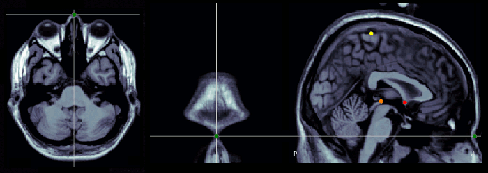
Pre-auricular points (LPA, RPA)
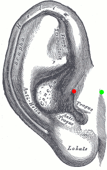
The proper definition of the preauricular point is: "a point of the posterior root of the zygomatic arch lying immediately in front of the upper end of the tragus". This is illustrated with the green point below. The problem with this definition is that it can be really difficult to localize precisely on the MRI. It can lead to severe misregistration between MRI and MEG/EEG. More information on the anatomical location of this point on the FieldTrip website.
Our proposition is to use instead the junction between the tragus and the helix, marked with a red dot in this figure. It can be located much more precisely both anatomically and on the MRI slices.
You can choose to use this definition of the "preauricular point" or not. The most important is to use the same convention for all the steps: digitization of head points (eg. Polhemus) and analysis with Brainstorm.
Use the sagittal orientation to define it.
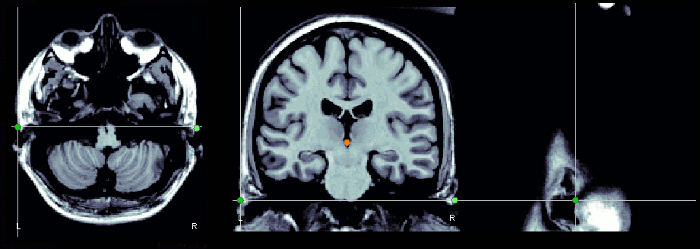
Notes for CTF users
Using a CTF system, you would probably prefer to use the head localization coils to indicate these NAS/LPA/RPA points, instead of these "anatomically correct" points. The coordinate system in the CTF files is based on the position of the three coils you stick on the head of the subject. Typically, the nose coil is slightly above the nasion, and the ear coils about one centimeter more frontal than the points that were previously described.
A good practice is to take pictures of the subject with the coils on, right before bringing him/her in the MEG, and digitize the position of the center of the coils as the nasion/LPA/RPA. Then, when importing the MRI in Brainstorm, try marking as accurately as possible the position of the coils in the MRI. You cannot be very precise at this point, but the errors here are fixed later with the automatic registration.
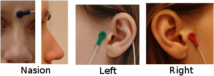
IMPORTANT: These comments do not apply if you use the Brainstorm Digitize program to drive the Polhemus device. In this case, you are asked to digitize two sets of NAS/LPA/RPA points: the coils and the real anatomical points. Just make a copy of the .pos file saved by Digitize in the .ds folder, then set the real anatomical points in the MRI. Brainstorm is going to automatically handle the transformation between the CTF coils coordinate system and the real subject coordinate system. The result is usually much more accurate and does not require to take pictures of the subjects.
Using a default anatomy
The fiducial points (Nasion, LPA, RPA) used in your recordings might not be the same as the ones used in the anatomy templates in Brainstorm (Colin27, ICBM152, FSAverage). By default, the LPA/RPA points are defined at the junction between the tragus and the helix, as represented with the red dot.
If you want to use an anatomy template but you are using a different convention when digitizing the position of these points, you have to modify the default positions of the template with the MRI Viewer.
- Go to the anatomy view
In (default anatomy), right-click on the MRI > Edit MRI
- Modify the position of the fiducial points to match your own convention
- Click on [Save], it will update the surfaces to match the new coordinate system
MRI coordinates
Coordinates system used to index voxels in the space of the MRI volume, in millimeters:
Axis X: left>right
Axis Y: posterior>anterior
Axis Z: bottom>top
- The first voxel at the bottom-left-posterior of the MRI volume is voxel (1,1,1). The coordinates of the center of this voxel in millimeters is (voxelsize_x, voxelsize_y, voxelsize_z).
World coordinates
Coordinates system used in the original MRI file, that was loaded as the reference MRI for a subject. It is defined by a 4x4 matrix saved directly in the MRI file. From NIfTI .nii files, it uses the matrix sform if available, or otherwise the matrix qform (see the NIfTI documentation). From FreeSurfer .mgh/.mgz files, it uses the vox2ras matrix (see the FreeSurfer documentation).
In practical terms, it corresponds to the coordinates you see in the title bar when loading your volume in MRIcron. The coordinates you see in the text boxes correspond in Brainstorm vocabulary to "voxel coordinates".
For subject data, it corresponds most of the time to scanner coordinates. For atlases, it may correspond to normalized coordinates (e.g. MNI coordinates).
MNI coordinates
In order to compare the anatomy of multiple human brains or compute group statistics, it is necessary to define a common reference system. Two types of normalized systems have been widely used in the literature in the past: the atlas defined by Jean Talairach, and the MNI stereotaxic coordinates. You can read about the differences between these two systems on that page: http://imaging.mrc-cbu.cam.ac.uk/imaging/MniTalairach
While the Talaraich system has been progressively abandonned, the "MNI space" has been increasingly used, thanks to the development of automatic normalization methods in open-source neuroimaging software. Successive updates to the reference brain and software versions led to the coexistence of multiple "MNI spaces". For an exhaustive list, please refer to these two websites:
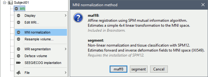
In Brainstorm, MNI coordinates refer to the normalized space defined in SPM12, also referred to as IXI549 space. There are two solutions available for obtaining MNI coordinates in the Brainstorm MRI viewer: a linear and a non-linear approach, both are computed using SPM12. Wheter you compute the MNI normalization from the MRI viewer or the database explorer, you get this message:
MNI: Linear
A [4x4] affine transformation is computed and saved in the MRI NCS structure:
R: [3x3] rotation matrix from the MRI coordinates to the MNI coordinates.
T: [3x1] translation matrix from the MRI coordinates MNI coordinates.
The function mri_normalize_maff.m uses code from SPM12 (spm_maff8 ©J Ashburner), described in the following article: Ashburner J, Friston KJ, Unified segmentation, NeuroImage 2005
- This transformation is fast to compute, fast to apply to 3D coordinates, and very light in terms of storage. It is appropriate for computing a deformation of the bounding box of the brain and adapted for quickly aligning brains in the same space. However, it cannot represent the differences in the cortical folding of the individual brains.
MNI: Non-linear
- Description
- Significant increase in file size: ...
As the reference anatomy, we use the ICBM125 2009c Nonlinear Asymmetric, as described in the tutorial Using the anatomy templates.
Talairach coordinates
> This is not much used in Brainstorm anymore. If we cannot compute the MNI normalization as presented in the previous section, we use an approximation to the Talaraich coordinate system. It relies on two points, the posterior and anterior commissure, and the midsagittal plane. The third point needed here, the interhemispheric point, is used to define this plane. You can read about the differences between these two systems on that page:
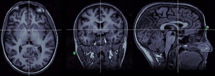
Description of the anterior commissure at this Wikipedia page. Technique to localize it:
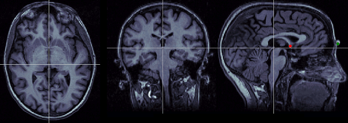
Description of the posterior commissure at this Wikipedia page. Technique to localize it:
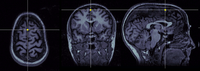
Pick any point in the interhemispheric space, somewhere in the top of the head. Do not use a point too close from the commissures.
This coordinates system is not used in Brainstorm, and described here only FYI. All the information contained in Neuromag .FIF files are in this CS, and converted to Brainstorm SCS at importation. It is defined in the following way: Based on: Nasion, left pre-auricular point (LPA), and right pre-auricular point (RPA). Origin: Intersection of the line L through LPA and RPA and a plane orthogonal to L and passing through the nasion. Axis X: From the origin towards the RPA point (exactly through) Axis Y: From the origin towards the nasion (exactly through) Axiz Z: From the origin towards the top of the head
The conversions between coordinate systems is handled with one single function cs_convert: sMri: MRI structure from the database: right-click on the MRI file > File > Export to Matlab > sMri All the the coordinates have to be in meters (not millimeters). Examples:
The .pos files generated with the Brainstorm Digitizer contain both the positions of the anatomical landmarks (nasion, left ear, right ear) and the position of the head localization coils (HPI). Having the two sets of points allows us to convert automatically from the native CTF coordinates (based on the coils) to the recommended landmarks in Brainstorm (based on the anatomical landmarks). When a Brainstorm .pos file is present in the CTF .ds folder, it is loaded automatically and used to convert the positions of the EEG and MEG sensors to the anatomical reference. This is done automatically without any message or user confirmation. In this case, you should mark the anatomical landmarks (real nasion and tragus/helix junctions) in the MRI Viewer when importing the anatomy. This is what is described in the introduction tutorials. Otherwise, if you are importing CTF recordings without a Brainstorm .pos file in the .ds folders, or if you are importing the .pos files after linking the recordings to the database, you should typically select the positions of the CTF HPI coils in the MRI viewer. The syntax of these .pos files is the following, one line per digitized point: In the .pos files, the anatomical landmarks are labelled Nasion/LPA/RPA, and the CTF HPI coils are labelled HPI-N/HPI-L/HPI-R (for nasion coil, left coil, right coil). Note that in the CTF software, the HPI coils are labelled NAS/LPA/RPA, which can lead to some confusion. We usually take multiple measures of each reference point and average them when we load the file. This helps improving the accuracy of the registration.
Tutorial: Channel file / MRI registration Forum: Bad MEG-MRI registration Forum: Coregistration validation Forum: Import the position of SEEG/ECOG contacts: Post #2206, Post #1958, Post #2357
Anterior commissure (AC)
Posterior commissure (PC)
Interhemispheric point (IH)
Neuromag coordinates
Converting between coordinate systems
Pdest = cs_convert(sMri, 'src', 'dest', Psrc);
P_mri = cs_convert(sMri, 'voxel', 'mri', P_voxel);   % Voxel => MRI coordinates
P_mni = cs_convert(sMri, 'scs', 'mni', P_scs);       % SCS   => MNI coordinates
Brainstorm .pos files
Number of EEG electrodes
Index   Label   X   Y   Z     : Defines an EEG electrode
Index           X   Y   Z     : Defines a head shape point
Label           X   Y   Z     : Defines a reference point
2
1       Cz       5.29886357      -0.39211620      13.97175211
2       Pz      -2.72999896       0.56457819      14.80592908
3                9.47286768       0.09984190      -2.22056385
4                9.61745050      -0.00705346      -2.64471836
[...]
242              2.68917264       3.02778502      13.88281027
243              1.10525214       3.54043941      14.17347208
Nasion   9.59228188      0.08328658     -1.88504105
LPA     -0.47469294      6.81987024      0.62870235
RPA     -0.96029260     -6.72333418      0.16475241
Nasion   9.76823213     -0.11917776     -1.87417223
LPA     -0.29274026      6.88415084      0.70120923
RPA     -0.99183277     -6.70128616      0.08443862
HPI-N   10.61990713      0.01532629      0.00407281
HPI-L    0.20165313      6.74350937     -0.00134360
HPI-R   -0.23124566     -6.76723759     -0.00008921
HPI-N   10.61095674     -0.01532629     -0.00407281
HPI-L    0.27017080      6.81335558      0.00134360
HPI-R   -0.24057827     -6.78962736      0.00008921
Additional documentation
