Hi everyone,
I'm trying to use Brainstorm to perform source analysis. When I upload eeg chanlocs these are not in the right position and I can't modify them. Does anyone have ideas about it?
Thank you,
Alberto
Hi everyone,
I'm trying to use Brainstorm to perform source analysis. When I upload eeg chanlocs these are not in the right position and I can't modify them. Does anyone have ideas about it?
Thank you,
Alberto
Hi @albertobenelli,
Please provide more information on what is happening, so we can assist you, e.g.:
Hi Ramundo,
Thank you for your reply.
The EEG file imported is a .set file.
I'm not using a default anatomy but a real MRI image.
Electrodes are based on the 10-20 eeg system
Chanloc is from a file.
Is your chaloc file in polar coordinates (.loc) is?
If this is the case, it indicates the location of the electrodes in the 2D sensor disk. Thus at importing these 2D locations are projected to a sphere that does not match the anatomy.
One way to address this is use EEG locations that have been aligned to the MNI152 (ICBM152) anatomy, and, and projected them to the Subject anatomy (which should be MNI-normalized)
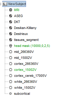
Import the MRI of the subject and perform MNI normalization
Import the EEG data
right-click on > Add EEG positions > ICBM152 > Generic > ASA 10-20 94
This will use the
Verify the location of the electrodes on the scalp:
Right-click on the Channel file (![]() ) > Display sensors > EEG head
) > Display sensors > EEG head
If further adjustment is needed (electrodes are not exactly on the scalp but a bit under of above) you can project them to the scalp surface: Right-click on the channel file > MRI registration > Edit and click on the button "Project electrodes on scalp surface (![]() ). More info in here:
). More info in here:
https://neuroimage.usc.edu/brainstorm/Tutorials/Epilepsy#Register_electrodes_with_MRI
Thank you for your reply Raymundo,
The result now has improved but still not perfect.
I also tried Right-click on the channel file > MRI registration > Edit and click on the button "Project electrodes on scalp surface and the result changed but it is not perfect.
Do I need do something different (I followed the tutorial) when I import the scan?
Thanks again
Alberto
Not really, only MNI-normalization would be needed
https://neuroimage.usc.edu/brainstorm/Tutorials/ImportAnatomy#MNI_normalization
Can you share a screenshot and describe the outcome you are having?
Thank you for your quick reply Raymundo,
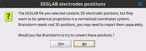
The steps I followed for the T1 are: 1) import the image 2) insert NAS, RPA, LPA etc. 3) normalize 4) save. For EEG file: loading the eeglab .set file: automatically, recognizes chanlocs. When I upload the file, I need to decide whether to have Brainstorm apply a conversion to the channels.
Then I applied your instructions and this is the result
An other issue is related to the eeg file. The eeg file is already epoched but since I need the file unepoched I found out the way to do that using the function "concatenate time", but I can visualize just 21.63s
How can I visualize the entire recording?
Thank you
Alberto
It seems the projection to scalp did not work.
Did you save the changes when closing the (channel-)MRI registration window?
When importing the EEGLAB file, In the window Import EEG-EEGLAB file be sure that the checkbox Get all epochs is selected and the checkbox Use events is not selected.
After concatenating, the resulting file should be as long as the EpochDuration × nEpochs
Thank you Raymundo,
I fixed the EEGLAB problem but not for the eeg chanlocs. DO you have any others suggestions? Which kind of parameters should I change to make the electrodes under the skull on top?
Thank you
Alberto
![]() the Projection of electrode on Surface should do the trick.
the Projection of electrode on Surface should do the trick.
Before importing the EEGLAB epochs:
After importing the Epochs:
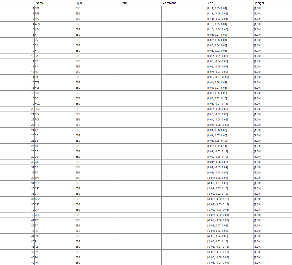
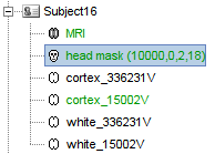
In the channel file, Right-click > Edit channel file, verify that all the EEG channels are labeled as EEG type. Make a save changes if needed. Also verify that they have names from the 10-20 international system. Can you share a screenshot of this?
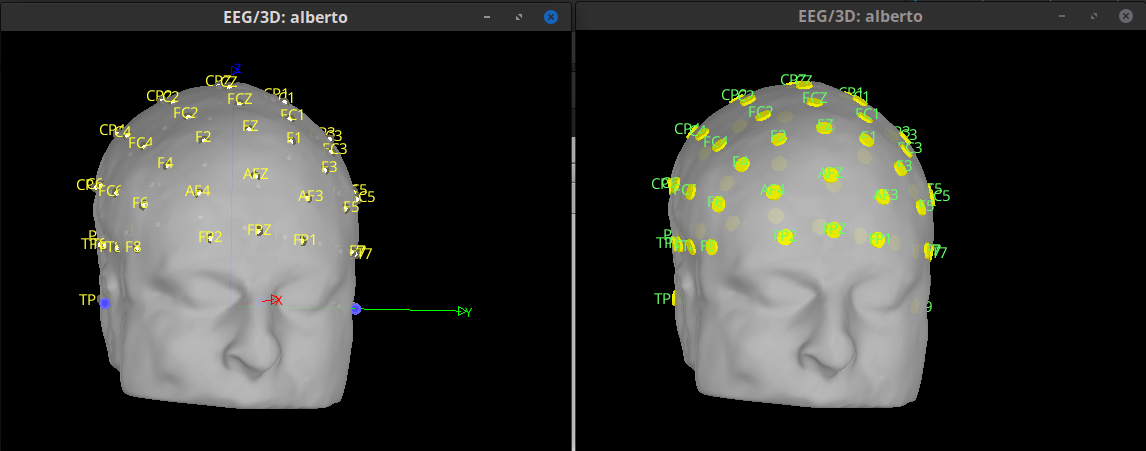
When the electrode locations have been added from the Generic > ASA 10-20 94 cap.
Is there any message that some electrodes were not found?
I have this window
This is strange.
Would it be possible to shared the anatomy folder and the EEGLAB recordings to further investigate? If possible, you can send in PM the a link to download the files.
About this question, was there any popup window?
When the electrode locations have been added from the Generic > ASA 10-20 94 cap.
Is there any message that some electrodes were not found?
Yes, sure.
No, there was not any issue popup window
Solved!
Convert positions? Select No. After all the channel locations were not polar (2D) for 3D, but they come from the projections on a uniform sphere, not positions in that were digitized. Thus we do not convert them as they will not be used.
Get all epochs
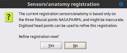
Refine registration now? Select No. Head points are from a perfect sphere, they will be useful to refine the registration.
Close the channel figure.
Add EEG channel locations:
right-click on > Add EEG positions > ICBM152 > Generic > ASA 10-20 94
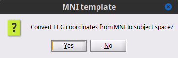
Select Yes as we want to convert convert the EEG coordinates from the MNI space (template cap) to the Subject space (individual's head).
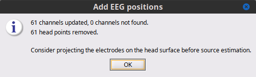
All channels (61) where updated, based on their 10-20-international-system name
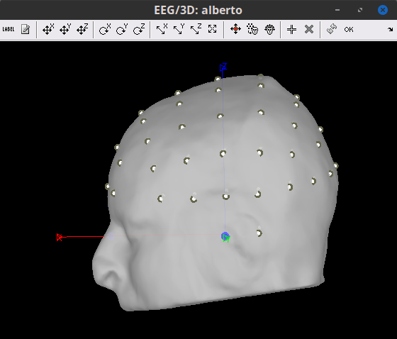
The electrodes are now in their position according to the MNI space, but need to be placed on the Scalp. Right-click on the channel file > MRI registration > Edit. Click on the button "Project electrodes on scalp surface (![]() ), then on the OK button, and save.
), then on the OK button, and save.
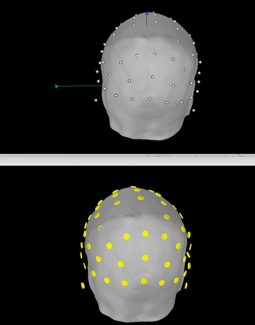
Before projecting to scalp

After projecting to scalp
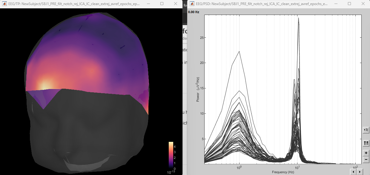
Thank you so much. I'm trying to visualize the EEG recording but something is wrong. I should see a peak in alpha band in posterior regions but I found it in anterior regions actually.
Can you see the same result?
Things look good, higher power in posterio regions.
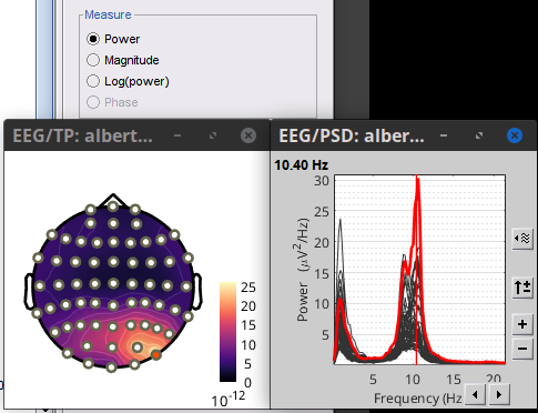
Maybe the source of confusion was the option log(power) which does 10*log10(power)
When created, the topoplot for power, shows Absolute values, when changed to log(power) option for Absolute values remained. It can be changed with right-click on the colorbar > Colormap: Timefreq > Absolute values )
Now Brainstorm automatically unchecks the Absolute values option when displaying log(power), commit 83e1d79.
Update your Brainstorm instance to have this behaviour.
Thank you so much, you helped me a lot.
How did you find it? Which steps did you follow?
Alberto