I am starting with new project based on patent technology the OPM -based magnetoencephalography ( MEG), and the team would like to do every thing in brainstorm,
I would like first to ask if someone solve the forward model of FMEG here so can get the leadfield matrix between the fetus cortex and electrode located on the abdominal skin of the pregnant women.
In fact Femonum project that can provide the meshes of the fetus, uteus, abdominal skin but they did not provide the MRI, I think it is possible to work with meshes with brainstorm, but the problem is they did not provide the mesh of the cortex of the fetus
Let say we have all the meshes and we want to import the meshes now to brainstorm, infact we have lot of surfaces more than 5, what is the maximum domain or surfaces openmeeg in the brainstorm can solve?
One proposition for the work is try to model two diploes simulating fetal brain and fetal heart dipole (as artifact) to analyze the sensitivity of OPM-MEG to fetal heart and brain signals before applying different artifact correction methods.
I am starting with new project based on patent technology the OPM -based magnetoencephalography ( MEG), and the team would like to do every thing in brainstorm. I would like first to ask if someone solve the forward model of FMEG here so can get the leadfield matrix between the fetus cortex and electrode located on the abdominal skin of the pregnant women.
I guess you mean "leadfield matrix between the fetus cortex and OPM sensors", not "electrode", right?
I don't know if the MEG forward models in Brainstorm can be transposed to OPMs. Let me ask the experts, we'll get back to you. @John_Mosher@Sylvain@tmedani@juangpc@labyt
Do you have any suggestion how to do it, in fact there Femonum project that can provide the meshes of the fetus, uteus, abdominal skin but they did not provide the MRI, I think it is possible to work with meshes with brinstorm, but the broblem is they did not provide the mesh of the cortex of the fetus
Let say we have all the meshes and we want to import the meshes now to brainstorm, infact we have lot of surfaces more than 5. what is the maximum domain or surfaces openmmeeg in the brainstorm can solve?
All these tissues should not affect much the MEG leadfields. Having only a few surfaces could be enough, maybe the abdominal skin and the fetus head.
We currently have new ongoing developments using FEM models, these could be helpful in this context as well. Documentation is not finished, but here is a draft so you can have an idea of what we are doing: https://neuroimage.usc.edu/brainstorm/Duneuro
One proposition for the work as written in task 2.2 in the attached image is try to model two diploes simulating fetal brain and fetal heart dipole (as artifact) to analyze the sensitivity of OPM-MEG to fetal heart and brain signals before applying different artifact correction methods. Is this will be possible with brainstorm?
How many sensors do you have?
If you have multiple sensors, you should be able to use SSP and ICA techniques to reject stereotyped noise or separate sources.
From my side, I think brainstorm LF computation is possible between the fetus cortex and OPM sensors , the principle is still the same.
However, I'm not sure that we have a model of the OPM sensors (file format and integration points). Also, the full geometry model of the fetus should be constructed outside of brainstorm.
To add more infos to Francois's answer.
You can use these available meshes and build your complete model and then import the final model to brainstorm. You can also merge/modify and align all these mesh surfaces from the brainstorm interface.
When you have all the geometry and channels models available, you will need the conductivities values of the tissues in order to compute the LF.
For the computation, you can use either the Opnemeeg or Duneuro. For openmeeg I think you can use up to 3 or 4 layers (check here: Tutorial — OpenMEEG). With FEM Duneuro, you can use as much as you want, but the recommended number is 5/6 layers. The effects of the tissues are discussed here : A guideline for head volume conductor modeling in EEG and MEG - PubMed
If you want to use the Duneuro, you can easily generate the FEM mesh from the surface with brainstorm.
For the layers to use, it depends, the EEG is more sensitive to the number of layers and theire conductivities than the MEG (refer to the previous Lew paper link).
There are already precise definitions for some types of OPMs in the coil_def.dat file. If a "three-axis measurement” means that you measure three different components of the magnetic fields with a single OPM, this translates to having three separate sensors at (about) the same location and (almost) the same geometry. In addition you need to take into account the possible cross talk between the sensors but this is a calibration-line adjustment not directly relate
The magnetic field due to radial sources outside a spherically symmetric conductor is zero. Therefore, the radial sources do not become visible even if you measure all components of the magnetic field.
@Saeed_Zahran What file format will you use to save your files?
If you had them in FIF, it would make things a lot easier for the import on the Brainstorm side.
In order to specify own sensors for the OPM 3 axis measurement, what Matti Hamalainen says about having three separate sensors at (about) the same location is very logic.
For example, If you look at the point magnetometer definition in the coild_def.dat file:
So as you know the first row is just some identifiers of the sensor. So a point magnetometer has, e.g., an id = 2000. The following rows define the sensor’s integration points, their weights and orientations. This sensor has one integration point at sensor coordinates (0,0,0) with orientation (0,0,1) and weight 1.0.
If we want to have multiple orientations at one point, I think we have to specified multiple sensor types. For example,
1 2000 0 1 0.000e+00 0.000e+00
"Point magnetometer"
1.0000 0.000e+00 0.000e+00 0.000e+00 0.000 0.000 1.000
1 2001 0 1 0.000e+00 0.000e+00
"Point magnetometer"
1.0000 0.000e+00 0.000e+00 0.000e+00 1.000 0.000 0.000
1 2002 0 1 0.000e+00 0.000e+00
"Point magnetometer"
1.0000 0.000e+00 0.000e+00 0.000e+00 0.000 1.000 0.000
Now this defines three sensors 2000, 2001, and 2002. They all have same integration points (0,0,0) and weights (1) but different orientations: sensor 2000: (0,0,1); 2001: (1,0,0); 2002: (0, 1,0). So this defines a triplet of orthogonal sensors. Now we can place to one position three different sensors 2000, 2001 and 2002 and they will all measure different orientations.
Now I am trying to understand how things goes in brainstorm and mne inorder to implement it, which it seems that it should work.
I am currently working on OPM forward modeling beyond a single point, for a specific prototype system. This is complicated to discuss generally however because many different flavors of OPM exist and it's not as simple as integrating the field over the sensing element (gas cell) as it is for SQUIDs (coil). The technology is based on magnetic resonance. The sensor I'm working on measures the atom polarisation precession frequency. Others measure light absorption/transmission. Both use one or more lasers. So we need to take into account many aspects: shape and size of the cell, directions of the lasers, intensity profile and diameter of the laser beams, and in my case integrating the signals with different phases and frequencies due to field inhomogeneities, and then taking the max spectral peak as the value extracted by the lock-in amplifier.
There are yet other considerations even with a single point approximation: the sensitivity of the design (1-d, 3-d, scalar), if it operates in earth's field, the effects of that field.
In my case, for simulations it's also non-trivial to model the noise. I have to look further into that.
So in conclusion, we need to know many details of a specific OPM design to properly model it, especially if we want to go beyond the single point approximation. So this might have to be done on a case by case basis.
I am return back to you to provide an update in OPM 3 axis measurement (forward model using brainstorm) and to ask a question, where we still need one step to be solved,
So following Matti Hamalainen's comment, we decided to use three separate sensors at (about) the same location.
I think the best start should be to follow the tutorial of vectorview already exist in Brainstorm ( Elekta-Neuromag tutorial: Median nerve stimulation, because as you know with vectorview they have 3 separated sensors at about the same location (2 Grad & 1 Mag).
If we look at the coil_def.dat, we will find the description:
Then if we load again the data and display the sensors, clearly we will notice the changes of the direction in the normal of the MAG (in yellow):
If we compute the leadfield matrix for both, clearly we will notice that the leadfield matrix is different between both, and this is a good indicator that the brainstorm can understand the changes done in the orientation we changed in coil_def.dat for MAG,
Now if we want to go back to OPM. With vectorview we have Grad and Mag, but with OPM we are dealing with 3_axis so we still need another axis.
I have read in brainstorm forum your reply on the integration of the file coil_def.dat to the channel file, where you shared the below link:
I started first to look at the both channel (by exported them to matlab) to see what is the changes, so the only change as expected is the orientation of Mag in all the channels,
So return back to the link you shared, I started with ctf_add_coil_defs.m after adding those lines in the coil_def.dat corresponding to what OPM should be:
But the issue, if you look at the rest of the code, I did not see where they integrated the orientation of the sensors corresponding the info in coil-def.dat, I saw Channel(i).Orient(:,1); but this is corresponding to the info in the channel file and I do not no how the orientation in coil_def.dat is integrated.
Can you please let me know what is the peace of code responsible in integrate the sensor orientation of coil_def.dat to channel file? or as you said on the same forum that even we do not need the coil_def.dat, so I just need to know how the orientation is calculated so that the forward model of OPM can be finally solved with brainstorm.
But again, why don't you simply edit the channel file?...
You may not even need integration points: don't you just need three sensors (= 3 Channel structures in the channel file = 3 rows in the F matrix fo the data file) with only one location (.Loc) one orientation (.Orient) each? For OPMx, OPMy and OPMz, the orientations would be orthogonal, with orientations that you know from your acquisition setup.
Btw, I recommend you only use one type of sensor (eg. "MEG OPM"), then if you need to identify them, use the names of the sensors (eg. ending with 1=radial, 2/3=tengential).
As I understand that the function Channel = ctf_add_coil_defs(Channel, systemName), takes the channel file as an input, so Channel(k).Orient(:,1) is corresponding to info in the channel file,
In the function they call the coil_def.dat as:
But I do not understand where/how they use the 0 0 1 here to link it with the orientation of the channel file? in the other word what is the equation (or link) between 0 0 1 and 0.1763 0.9843 -0.0130 (the orientation of the channel 1 in the channel file for instance)? when I understand this, then I can simply edit the channel file as you recommended
Yes we want to use one location (.Loc), one orientation (.Orient) for each, as I discussed with Etienne Labyt. I will follow your recommendation regarding the naming of the OPM sensors.
This function creates multiple integration points from the center of the sensor. All the integration points in one sensor always have the same orientation vector, they only have different positions (.Loc) and direction (+/- coil directions defined in the .Weight field, for gradiometers only)
This is the channel number 3 in the vectorview (which is the MAG), without changing in the coil_dat.def (keeping the orientation 0 0 1)
channelunchange.Channel(3).Orient
This is the channel number 3 in the vectorview (which is the MAG), with changing in the coil_dat.def (the orientation from 0 0 1 to 0 10 ) as I explained above
channelchange.Channel(3).Orient
So if the Orient field is coming from the initial channel file and remains unmodified, why this changes happen? I just make a modification in the coil_def.dat for vectorview MAG and reload the raw.fif file,
can you please explain this point?
As I am making a simulation study so I will generate the orientation of the sensor. The things begin more clear for me now, I just need to know why the orientation is differ above?
You were asking about ctf_add_coil_defs.m, I replied about ctf_add_coil_defs.m: it does not modify .Orient.
This is a simplified version of mne_load_coil_def.m we added just in Brainstorm for some very specific purposes. Indeed, you should not be referring to this one if you are changing the last 3 values of the sensors definitions in the coil_def.dat.
Either you debug this line by line, and it will be long and painful. Or you just write your own channel file, because you actually don't need any of this crazy complexity.
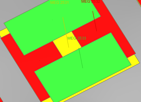
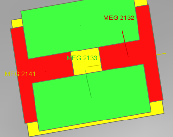
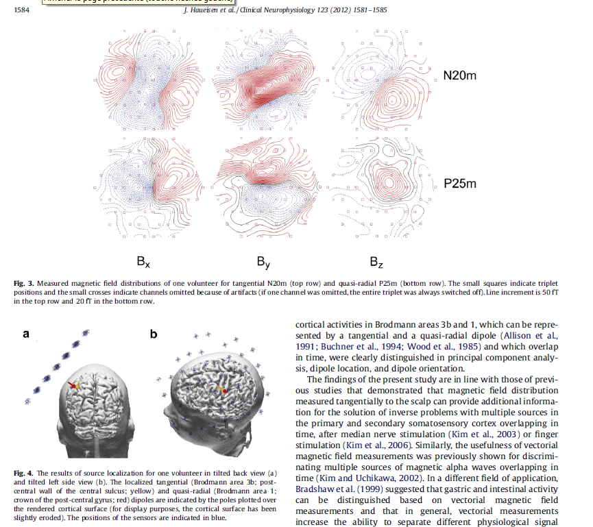
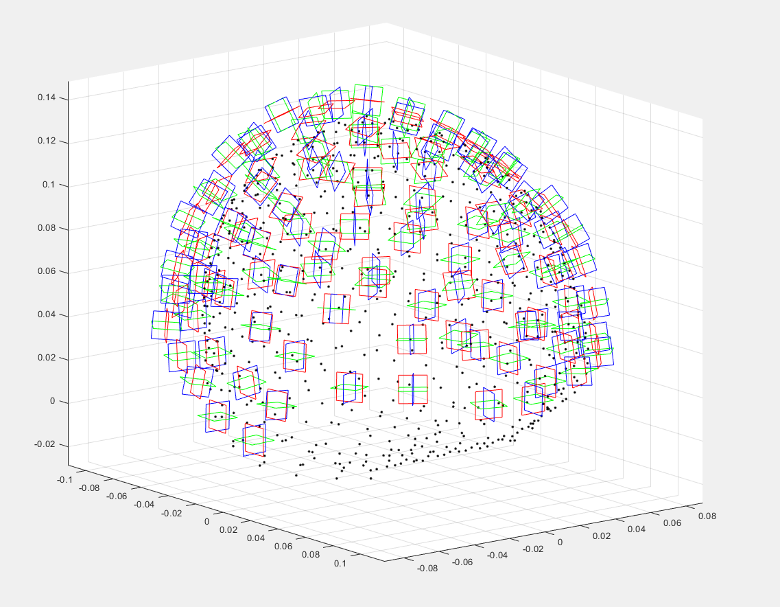
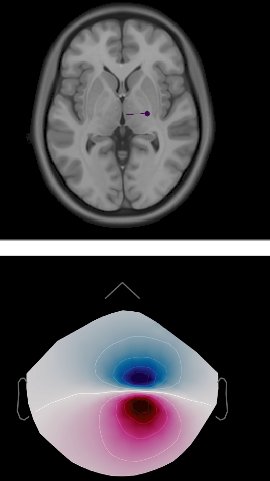
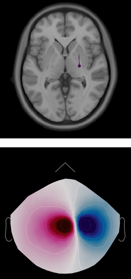
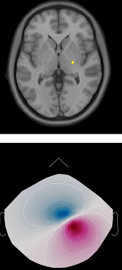
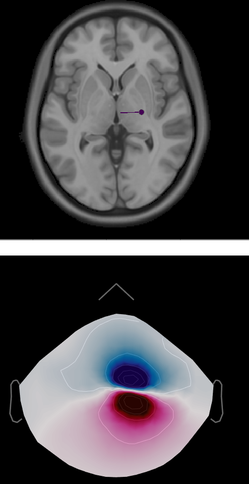
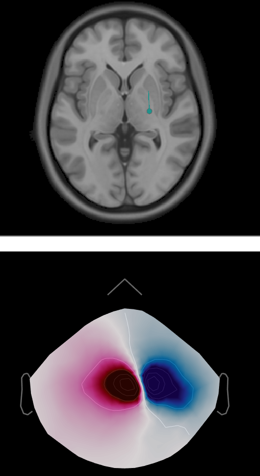
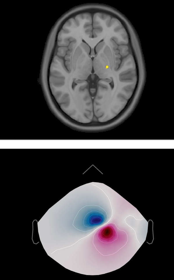
then solving the forward model for OPMn (normal orientaion of the sensors), OPMt1 & OPMt2 (tangential direction of the sensors), by choosing one dipole with 3 orthogonal orientation and by projecting it towards the sensors unfortunately we did not see the changes in the 2d sensor cap interms of flipping of the red and blue spot between OPMn, OPMt1, OPMt2,
So I decided to put 4 integration point (as the example of the SQUID in Brainstorm) instead of one,
The new configuration is like the figure below, so 3 squares with different direction coresponding to OPMn, OPMt1, OPMt2, because I thought that maybe brainstorm will not understand that I am modifying the orientation when we deal with just one point,
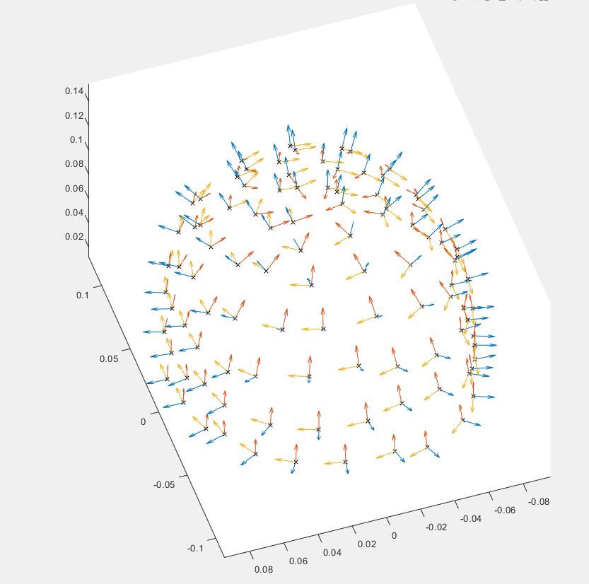
I'd have to see the 3d view of the dipole and sensors to see if it makes sense or not. Probably best to keep things as simple as possible to start with, like a single sphere head model. Also are you certain your OPMt1 faces the same way as in the figure you are comparing to?
I'm not sure I see what is wrong with your experiment. The 2D topographies you obtained look compatible with the orientation of the dipoles you simulated.
Make sure you took into account the fact that by default, the MEG fields are represented on a surface of virtual magnetometers. https://neuroimage.usc.edu/brainstorm/Tutorials/ExploreRecordings#Magnetic_interpolation