Volume source estimation
Authors: Francois Tadel, Takfarinas Medani, John C Mosher
The default approach for the source estimation in Brainstorm is to limit the source space to the cortex surface. This choice is motivated by the assumption that most of the activity we record in MEG and EEG comes from the cerebral cortex. Constraining the source reconstruction to a surface works well when this assumption is verified, and the results we obtain are much easier to review than a full volume.
However, when studying the activity from deeper regions of the brain or when processing recordings from patients with serious anatomical abnormalities, this cortical constraint is not always adapted. This tutorial explains how to construct a grid of dipoles that samples the full brain volume.
Contents
Compute a volume head model
The example below uses the protocol TutorialIntroduction created in the introduction tutorials.
Select the protocol TutorialIntroduction. Go to the view "Functional data (sorted by subjects)".
In the imported Run01, right-click on the channel file > Compute head model > MRI volume.
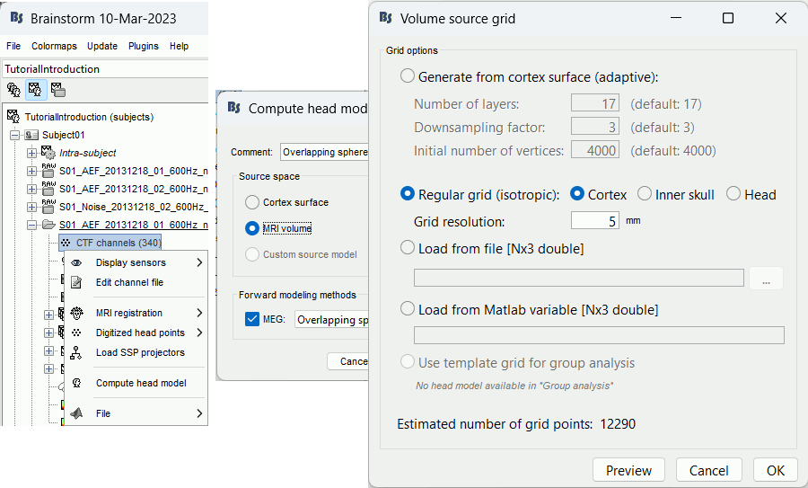
Generate from cortex surface: Creates a grid that samples the brain volume in an adaptive way, denser at the surface (we expect a higher spatial resolution close to the sensors), and sparser at the center of the brain. This grid is created with following algorithm:
Start with a brain envelope with a given number of vertices (Initial number of vertices).
Shrink the previous layer, and downsample it by a given factor (option Downsampling factor).
Repeat this operation [Number of layers] times, or until there are no more vertices.
Regular grid: Creates a regular grid with one grid point every few millimeters (option Grid resolution) in the three directions (x,y,z). The grid points are contrained to be located within the cortex surface, the inner skull surface, or the head surface.
Load from a file/variable: If you already have a grid of points you would like to use, you can import it from a file or a Matlab variable (only one field, [Npointsx3] values).
Use template grid: This option is only available when a template source grid has been defined on the default anatomy. For more information, see the tutorial Group analysis: Subject coregistration.
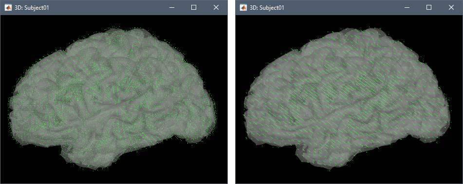
Preview: For each combination of parameters, you can see the total number of grid points at the bottom of the option window. Click on [Preview] to see the grid. The screen captures below show an adaptive grid (left) and a regular grid (right).
Leave all the intial options and click [OK]. A new head model is computed.
Compute sources
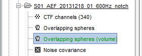
- Make sure your new volume head model is selected as the default one (displayed in green).
Right-click on this head model > Compute sources [2016] > Unconstrained dSPM.
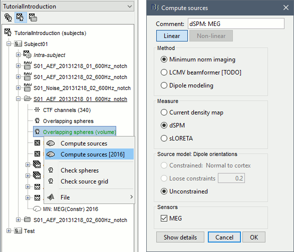
Note that only the Unconstrained dipole orientation is available. In the previous tutorials, the source space was the cortical surface, and we were able to use the normals to this surface to constrain the model. For a random grid of points, we cannot privilege one orientation more than another. Three orthogonal dipoles will be defined at each point of the grid.
Right-click on the dSPM sources for the Deviant average > Cortical activations.
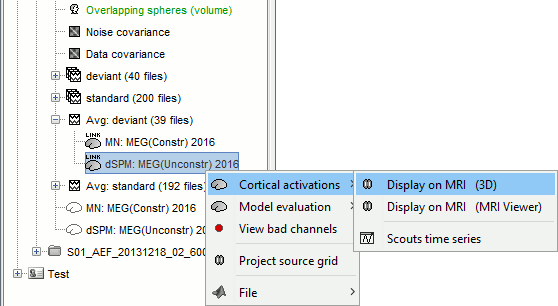
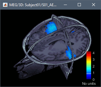
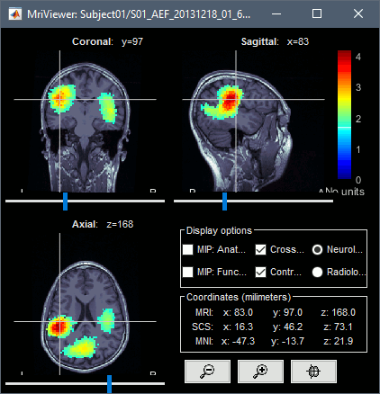
The two menus Display on MRI (3D) and Display on MRI (MRI Viewer) were already introduced in the tutorial Source estimation. You can use the sliders in the Surface tab to adjust the display. The bilateral response in the auditory cortices is very clear starting from 60ms.
Volume scouts
The regions of interest on the surface were introduced in the tutorial Scouts. In a similar way, we can also create regions of interests from the volume sources. In this context, a scout is a subset of the the grid of points used to estimate the sources. We cannot create them in the default atlas "User scouts", which is reserved to scouts created directly on the cortex surface.
Right-click on the dSPM sources for the Deviant average > Display on MRI (3D).
Go to 60ms and in the Surface tab, set the amplitude threshold to 20%.
From the scout tab: menu Atlas > New atlas > Volume scouts.
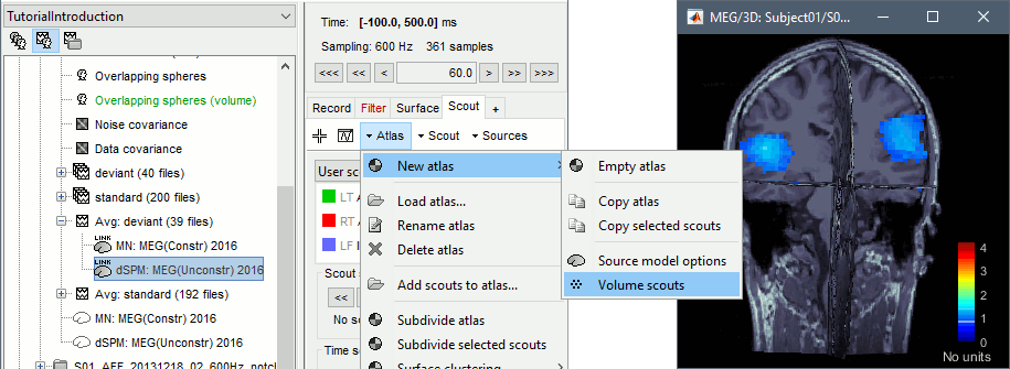
- Note that this volume atlas will be valid only for this grid of sources. If you compute another volume head model with a different grid, this atlas won't be available. To help you keep track of this, the name of the new atlas includes the number of grid points (eg. "Volume scouts 15004").
You can start drawing scouts with the 3D figure: Click on the button [Create scout], then click on one of the slices to define the center of your scout. The interface detects the coordinates of the point you clicked in the MRI and finds the closest point in the source grid.
To be able to select the region you want, you need to move the slices before creating the scout: right-click and move the mouse in the direction of the slice, or use the sliders in the section Resect in the Surface tab.
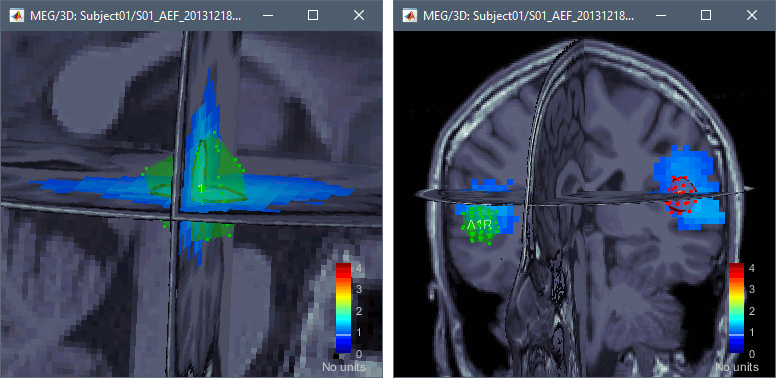
Grow the ROI with the buttons in the Scout tab ([<<], [<], [>], [>>]) and rename it (double-click). The dots represent the points of the grid that are part of the scout. The surface around them is their convex envelope, to give an idea of the spatial extent of the region.
Create two scouts for the left and right primary auditory cortices: A1L, A1R.
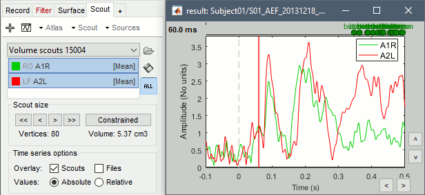
Display the scouts time series (first button in the Scout toolbar). With the option "Values:Absolute" selected, the values are averaged separately for the three orientations (x,y,z), then the norm of these three orientations is displayed: sqrt(x2+y2+z2).
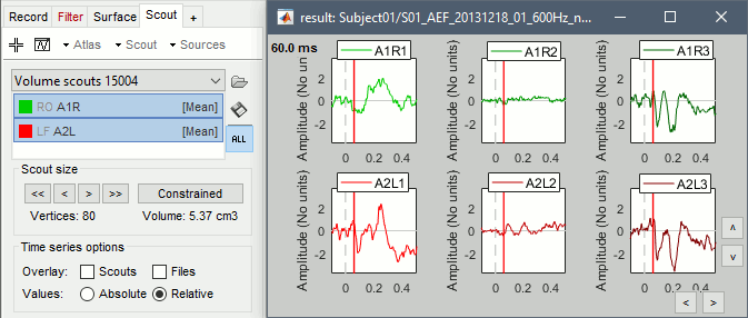
If you select the option "Values:Relative", you can observe the amplitude along the three orientations separately instead of the norm.
Volume atlases
From subject anatomy
The volume parcellations available in the subject anatomy folder can be converted to volume atlases from the Scout tab, with the menu Atlas > From subject anatomy. These parcellations can come either from MNI-based atlases or from individual anatomy segmentation (CAT12 or FreeSurfer). To obtain a volume atlas, you must have volume source maps opened, otherwise this menu would create a surface atlas.
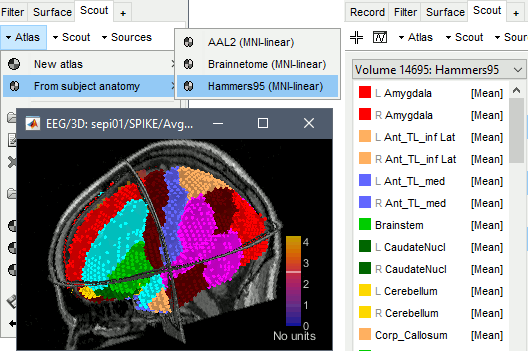
Subject space
Volume atlases in subject space (eg. FreeSurfer's Aseg atlas) can be loaded as volume scouts.
In the Scout tab: Atlas > Load atlas:
Select file format: Volume mask or atlas (dilated, subject space)
Select file: freesurfer/mri/ aseg.mgz.A new volume scout is created for each label in the atlas, including the sources located inside the labelled region. Remove or hide the cortex and white matter to see the subcortical regions.
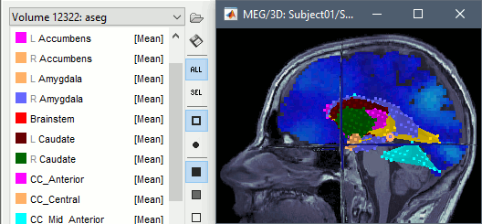
MNI space
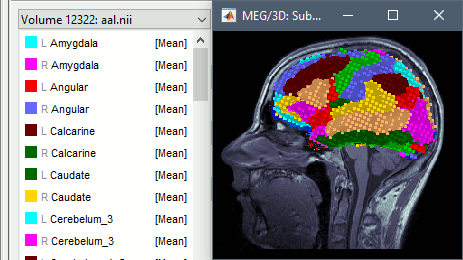
Volumes in MNI space can be imported and transformed to the subject space. Therefore you can also import as scouts any standard volume atlas, such as the AAL atlas. You just need to make sure you select the file format "Volume mask or atlas (dilated, MNI space)" in the import options.
To get the labels of the atlas displayed correctly, a .txt file with the same name should be present in the folder. Each line in this file must include the index of the label ("label_index label_name"), such as the atlases distributed as part of the MRIcron software.
Dilated vs. No overlap
When importing a volume atlas, you have the option to dilate or not to dilate each ROI mask (the voxels associated with this ROI in the input volume) before it is converted into a scout (a list of the indices of grid points). This adjusts the import method depending on what you are planning to do with these scouts.
No overlap: Each point of the source grid is associated with one and only one scout, as it was in the imported atlas volume. You should select this option if you want a strict parcellation of the source grid, eg. if you are using all the scouts at once, this avoids any unnecessary signal mixing between different scouts.
Dilated: The spatial sampling of the source grid is typically much lower (~5mm) than the resolution of the volume atlas you import (~1mm), which may cause small ROIs to disappear completely. If you are interested in one small ROI of the atlas, it might not be associated with any source point, and you wouldn't be able to retrieve any source signal for it. To ensure most ROIs are attached to at least one grid point, this option dilates each ROI before it is associated with points of the source grid. This option creates overlap between the scouts, which causes most grid points along the edges of ROIs to be associated with two or more scouts.
Mixed models
Volume scouts can also be created from the volume regions of a mixed source model, as described in the Deep Brain Activity tutorial.
Group analysis
If you estimate separately the sources on a volume grid for multiple subjects, you will most likely obtain different grids, that you will not be able to compare or average across subjects, and that you will not have the option to project on a template.
The easier solution for group analysis is to create a source grid at the template level and project to the individual subject spaces. This procedure is detailed in the tutorial Group analysis: Subjects coregistration.
Exclusion zone
In some cases, particularly with intracranial EEG (iEEG) such as sEEG and ECoG, where the source space is close to the sensor position, it is observed that the lead field of a source near the sensors can show unstable values or values significantly more extensive than those of neighboring sources. This issue is mainly due to numerical singularities as the distance between the source and the sensors approaches zero. These instabilities can lead to errors in source estimation when solving the inverse problem. Brainstorm allows us to remove all these "unstable" sources by creating an exclusion zone around sensors.
View and Check Leadfield
Brainstorm can display the lead field vectors. Once the lead file is computed, you can right-click on it and then > view the lead field. You can hit the "H" keyboard and display all the possible options.
Apply Exclusion zone
Once the lead field is visually evaluated, the user can determine if some of these lead fields are incorrect. Users can decide to remove from the lead field matrix. Right-click on the LF, then > Apply Leadfield Exclusion Zone > define a distance in mm. Brainstorm will detect all the sources within this distance remove all the corresponding LF, and then save a new LF model to the database.
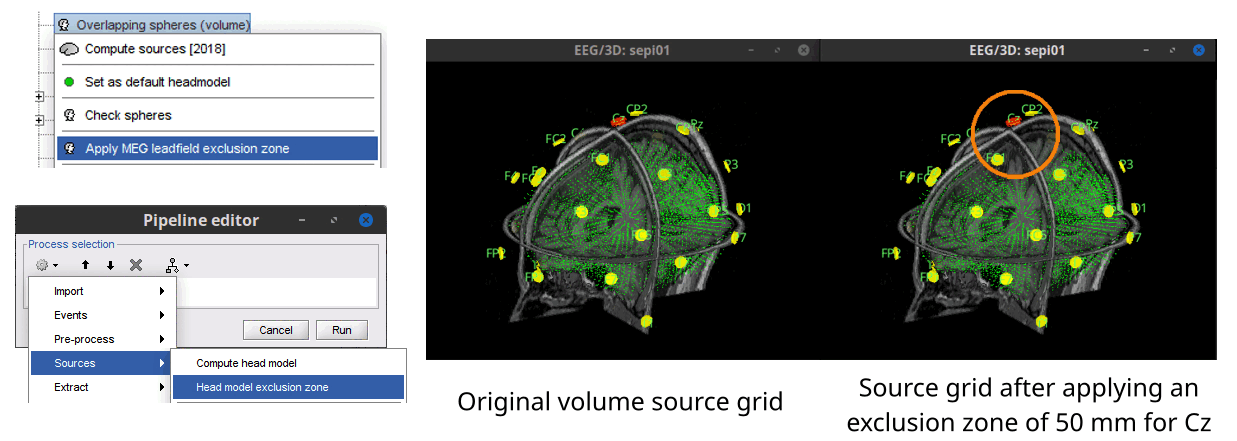
Alternatively, the exclusion zone can be applied with the process Sources > Head model exclusion zone, by using the process besides applying the exclusion zone of a sensor modality, it is possible to apply it for a subset of sensors. The figure below shows the ways of applying the exclusion zone, and the results of applying an exclusion zone (orange circle) of 50 mm around the EEG sensor Cz (in red).
Additional discussions on the forum
Warning: Dipoles outside the BEM layers: https://neuroimage.usc.edu/forums/t/36311
Scripting the import of volume atlases: https://neuroimage.usc.edu/forums/t/36708

