Dear experts
Hi
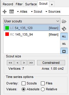
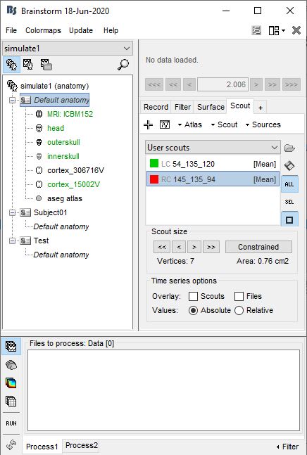
I'm going to know what is the relation between the scout vertices and the brain grid. indeed I've created two scouts with 7 vertices for both of them and I associated them two sinusoidal signals without any noise.
also, I've calculated a leadfeild matrix by openMEEG BEM by 15002 grid points. now, I have two questions:
I didn't select scouts on the cortex surface, they selected in the whole of the brain volume so what is the relation between scouts and brain grid? Am I wrong somewhere? I think that 7 scout vertices should be related to brain grid points.
I'm going to export leadfeild and scouts to MATLAB and multiple scout points to related leadfeild columns in order to obtain electrode recordings.
How can I do it? I think that the answer to the first question can help me to do that.
I appreciate your guidance.
Best wishes
Morteza
The following two forum threads might help you a bit better in simulating the signal from the scouts:
Brainstorm can obtain these electrode recordings natively so you don't have to do that via Matlab.
Indeed the scouts take vertices of the parcellated brain and when a signal is imposed in a scout all the source points in that will get your simulated signal imposed on them and via the Leadfield they are propagated to the electrodes.
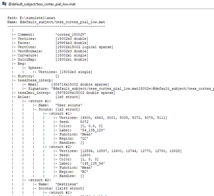
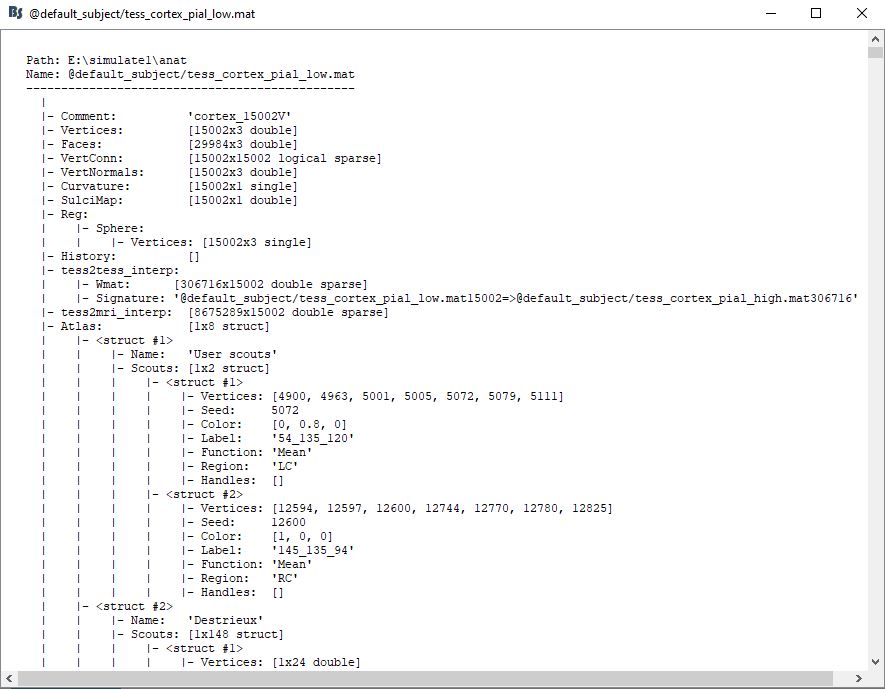
Each scout is a selection of a few of grid points = source space = the locations where the leadfield was estimated. The scouts are saved in the cortex surface, the list of elements they include is listed in the field Atlas(iAtlas).Scout(iScout).Vertices: https://neuroimage.usc.edu/brainstorm/Tutorials/Scouts#On_the_hard_drive
The indices in the field Vertices are related to rows in the following matrix:
Dear Francois;
I'm going to know that what is the relation between scouts coordinates (for example 54_135_120)
and GridLoc arrays.
For instance, if I want to simulate one of the scout's effects on a certain electrode on the scalp, I need to know which row of Leadfeild matrix (array of OpenMEEG BEM.GridLoc) is related to scout location and electrodeposition.
When I check the GridLoc arrays, their values are not related to scouts' location values (54_135_120)!
where am I wrong?
"54_135_120" is not the "scout location", it's the scout name.
This seems to indicate that you created the scout with the menu "Scout > New: coordinates". These values represent the coordinates of the scout's seed in the coordinate system that you used to create the scout.
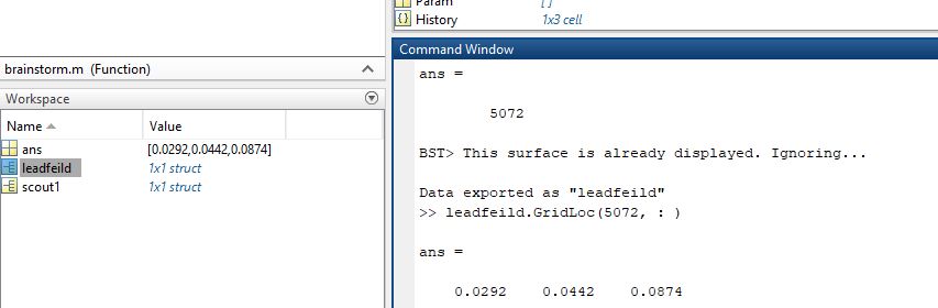
supposing the seed is the center of scouts, in the above scouts' information (as example 54_135_120) the seed vertex number is "5072"
after that, I exported "OpenMEEG BEM" to Matlab as "leadfeild" and for finding the SCS coordination of location of this vertex (i.e. 5072), I looked forward to "leadfeild " arrays. as I've showed bellow I wrote this command "leadfeild.GridLoc ( : , 5072)". is it the location of the center of scout? am I right?
If it's right, I'm going to obtain the electrode recordings (64 channels) from this scout in Matlab environment. in other word, I want to create electrode recordings by myself using Matlab. I think that I must to convolve scout's simulation signal (leadfeild.GridLoc ( : , 5072)) to "leadfeild.Gain", but the dimension of these arrays aren't match! how can I do that?
I'm sorry, I don't understand what you mean by "using a surface source model". if you mean that the source(scout) are just located on cortex, No, I'm going to locate different sources in whole head volume. please clear for me what you mean.
Thank you dear Francois. I looked at this code and tried to find what is the function of this code. Is this code going to simulate EEG electrode recordings by multiplying the forward model with the sources?
If it is right, I think that in this code the number of channels and electrode positions on the scalp are determined by forward model, and source signals are determined by the simulated signals those are assigned to scouts. is it right?
another question is that do I must export forward model and scouts' signals to Matlab and input this information on the "bst_simulation" function? could you please send me an example?
Thank you Francois,
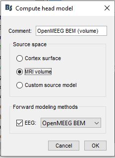
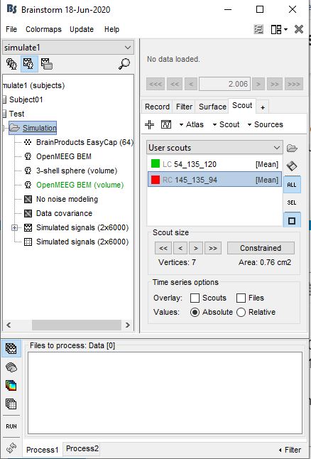
I'm faced with another problem, I selected a standard 64 electrode cap and then calculated the volume head model as:
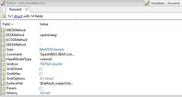
The forward model obtained as below:
as you see it has 15670 grid points with 3 dimensions and the Gain of the forward model has 47010 (15670*3) array for each electrode. I searched on Brainstorm's tutorials and discussions to find the relation between grid point arrays and forward model arrays. in another word, I want to know that which arrays of the forward model matrix are related to which array? for example, wich arrays of the forward model matrix are related to scout center 5072 as a grid point. finally, I aim to convolve this array to scout center 5072 to obtain the effect of this source on 64 electrode recordings.
The Gain matrix is the most important piece of information in the structure. It stores the leadfields for 3 orthogonal orientations (x,y,z) at each grid point (p1, p2, etc). The information relative to each pair sensor <-> grid source point is stored as successive columns of the matrix are ordered as: [ p1 _x, p1 _y, p1 _z, p2_x, p2_y, p2_z ...]. For the tutorial introduction dataset, with 15002 sources, the gain matrix has 45006 columns.
With this information, you can find the grid points that you want to use.
You can do this graphically by selecting the cortex with the scouts and then with right mouse button get coordinates . That will give you the vertex number. To do this automated I would not know to be honest.
as you mentioned I can find the coordinate that is related to an arbitrary vertex. But my problem is on using the whole of the brain volume and volume forward model.
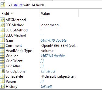
as you see, BrainStorm is calculating the volume head model as OpenMEEG BEM(volume), when I export it to Matlab, it shows:
two options are important for me, the first option is GridLoc that is having 15670 grid points in the brain volume and the second option is Gain of the head model that is related to grid points (15670 points) as you guide me in the previous comment.
As I told before, I'm going to simulate scalp EEG recording. So when I refer to scouts' information, I find two scouts center (5072, 12600).
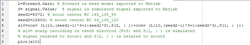
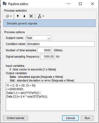
I use this information and the Gian matrix of the head model to simulate scalp EEG recording. therefore I export simulated signals to Matlab and convolve them by the Gain matrix columns that are related to scouts center. Matlab programming is:
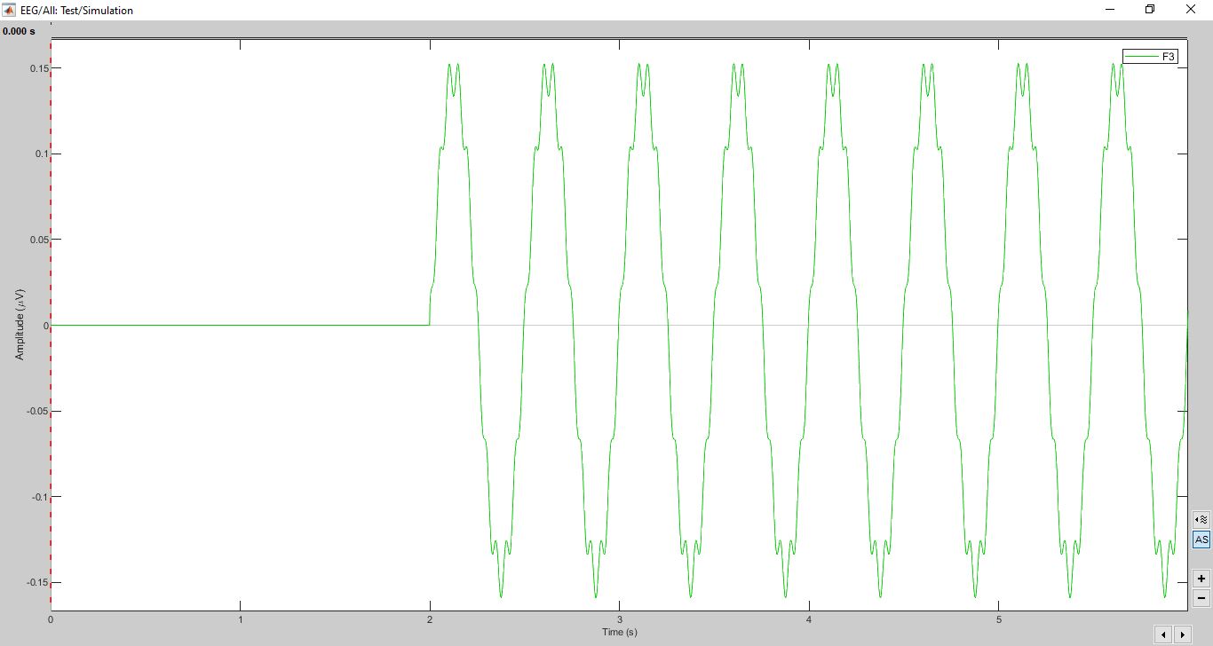
considering to simulate generic signal, I assigned data(1, : ) to scout2 and data(2, : ) to scout1.
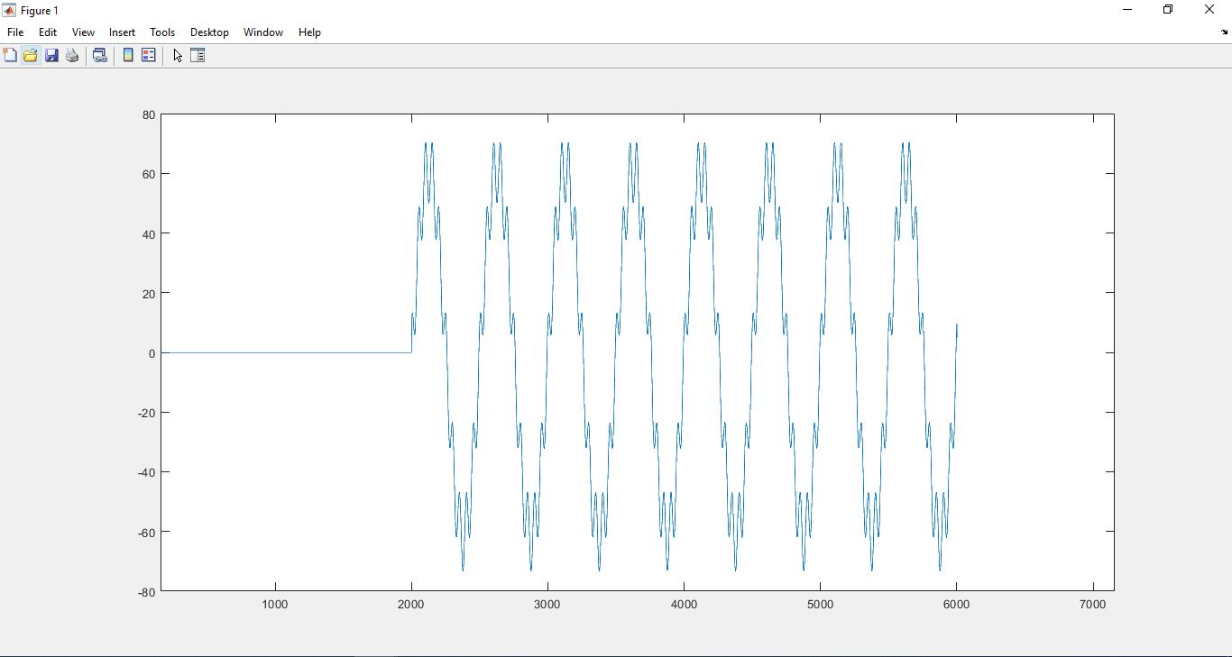
I have 2 questions by comparing this 2 recorded signal:
why the effect of scout2 in my program is more than BrainStorm result? (distortions on signal)
and how can I normalize amplitude as calculated by BS?
sorry for my long question
I appreciate your response
best wishes
Morteza
The lead field matrix should have elements in the order of magnitude of 1e-6 , so every signal with a unit amplitude should not give an output in the order of 1e3 as you now have. I don't know why you use the conv function, since it is a direct multiplication with your source signal (Measurement = LF*Sources).
Why the effect of scout 2 is bigger I wouldn't know to be honest, as far as I know brainstorm uses every vertex in a scout to simulate so that might lead to a difference.
Dear Steven,
So I must multiple lead field matrix array with order 1e-6?
and about using conv, I have a communication background so I think that because we have the environment transition model (lead field matrix) and the source signal, we must use conv for obtaining measurement. now, if I want to use multiplication, the dimension of leadfeild array and source signal are not match for multiplication operating. How can I do it?
No, if correct your leadfield matrix elements should have a magnitude of more or less this. Don't scale your leadfield matrix.
I can see the communications background, in which you would convolve using an impulse response. In this case however you can see it as a static gain. The lead field matrix does not contain time.
The leadfield matrix is in the order of #electrodes*(3*#sourcepoints), in your case 64*(3 * 15670), if it is unconstrained. (In constrained sources the 3 becomes a 1 since the dipole orientation is fixed then) Your source matrix thus should be (3 * #sourcepoints) * time if you want to end up with a matrix that is #electrodes*time
Which probably means a matrix full of zeros and at the rows corresponding to the vertices you put in the time series of your source.
Hope that answers your questions
Kind regards,
Steven
Dear Steven,
first of all, again and again, thanks for your replies,
I did all the things you suggested but the results are different from BrainStorm results. could you please help me more? how can I multiplicate forward model arrays with scout's simulated signal? I have tried in several ways but the results were different.