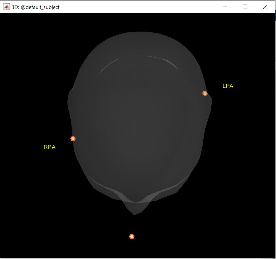
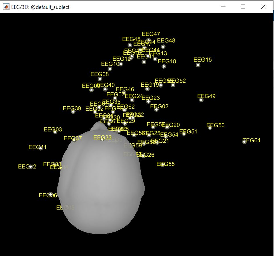
I have been trying to digitize the EEG electrode locations using a default headmodel but everytime i get unaligned LPA and RPA locations. I have attached the locations diagram. Kindly suggest any solution.
BTW, currently i am usng Colin27 headmodel.
Please provide more details about your request.
How do you proceed, step by step, what is your hardware, etc...
We are using Polhemus Fastrak hardware to collect the values. I am using the configurations and setup mentioned in the following link:
https://neuroimage.usc.edu/brainstorm/Tutorials/TutDigitize
Currently, I am using a dummy head to collect the points, but on every trail I get the same unsymmetric points as mentioned in the post above. I tried adjusting the location of head and the transmitter, I run the application on different devices but the results were same.
A few preliminary questions:
Are you using Brainstorm to collect the points?
Do they look "normal" when collecting?
What are you showing only has 3 points so I'm not sure what figure that is, 3 points wouldn't be enough to warp the default anatomy.
I would suggest trying to determine first if the issue is with the collected data or the warping that occurs in Brainstorm. Are you able to display the head points before warping the anatomy? Does it look like what you expect, similar to while collecting? Also, can you look at the range of values of those coordinates, to make sure they're in the correct units?
Yes, I am using Brainstorm to collect the points. I have observed one interesting thing while collecting these points, which is, when I am done taking the values of Nasion, LPA and RPA, before plotting the points on the head model it modifies or scales all the values. I am not sure if this is a normal procedure but it does some kind of alignment.
Yes it changes the coordinate system once you have collected these points, and the coordinates are then saved in the "head" coordinate system.
It would be helpful to view the head points (electrodes) before and after the Brainstorm warping procedure.
1 Like
I have showed just the reference points(NAS, LPA and RPA) in the figure above as the EEG electrode values further complicate the reading. The individual electrode locations do not seem to be in the actual place where they should be.
But is that before or after warping the anatomy?
What do you mean by before and after warping the anatomy? Can you please explain it a bit?
Ok so the problem is while collecting, not while importing and analyzing data, correct? I was commenting on the latter, sorry.
I think this is a Polhemus issue, either a hardware problem (likely) or wrong configuration (look at the volume it's trying to detect, only half the space around the emitter is in the acceptable zone). You can try testing it separately from Brainstorm. They have a software you can download. Please search for Polhemus on this forum, there was a very recent discussion about this that might help. Or contact Polhemus support.
1 Like
Yeah, I just looked up in tutorials and I can say that the above data points are taken before warping the anatomy.
I will look for hardware issues or any possible misconfigurations. Thank your for your time.
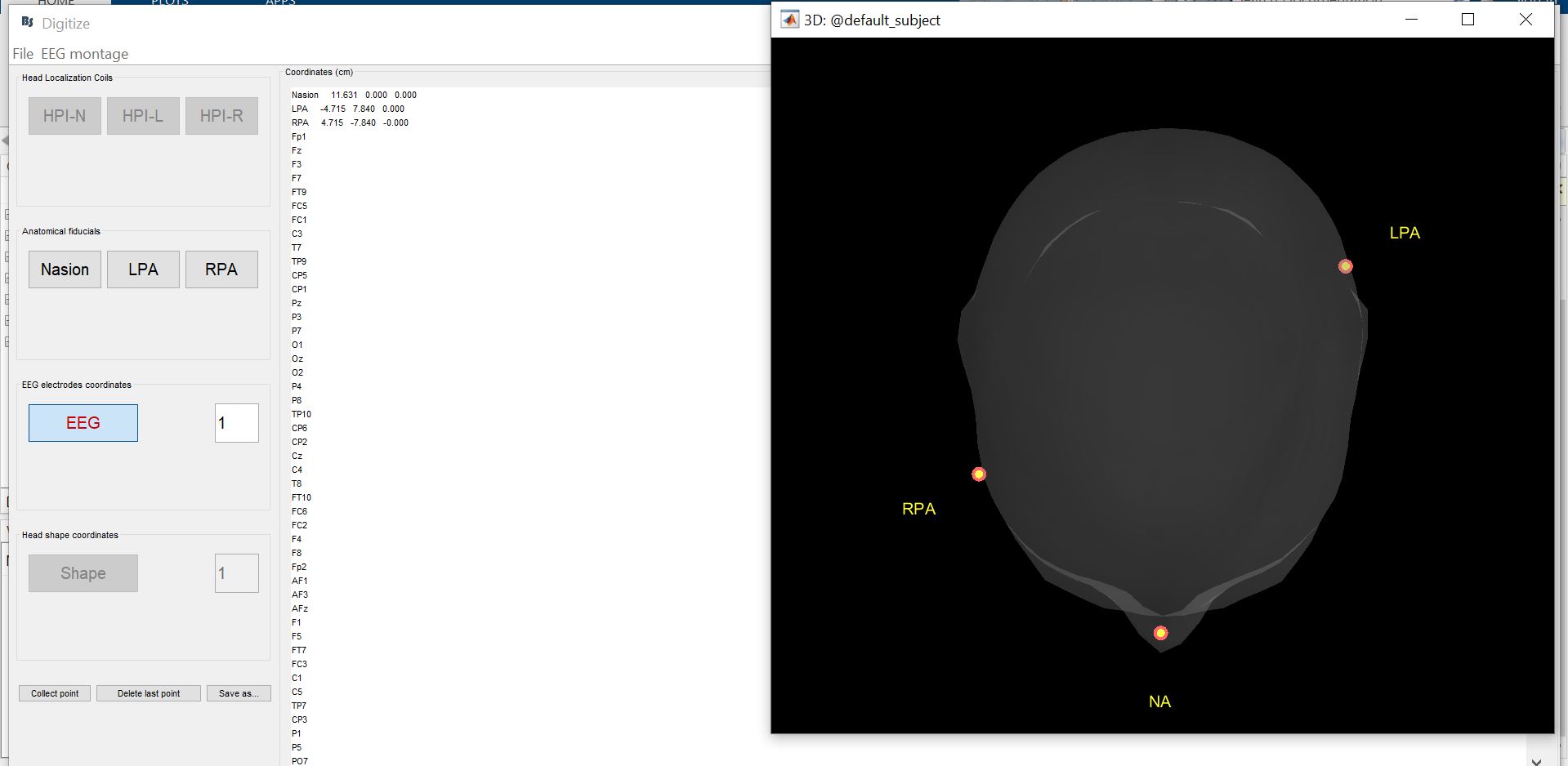
I was curious, the coordinate points seem aligned on the left yet the 3D head model doesn't represent them correct on the right. I checked the Polhemus Fastrak stylus, it looks ok.
The coordinates are also skewed, with both x and y values not near zero. But I'd have to look at the code as to how they're displayed on the head at this stage, probably projected to the intersection of the axis with the surface.
When you said the stylus "looks ok", did you test it in another software? Polhemus' PiMgr also allows you to easily access their hardware's "self tests". Please make sure that you don't have errors there: it's not useful to try to debug software if the hardware is broken.
If you've confirmed the hardware works as expected, including checking coordinates collected in PiMgr for example, then next would be to confirm the Polhemus configuration is correct as I mentioned, including importantly the side of the emitter you're collecting in.
Regarding the configuration, I've edited our code to set more parameters through the serial connection, to avoid having to (re)set them elsewhere. In the Brainstorm file panel_digitize.m, in function CreateSerialConnection, I added these lines to configure the Fastrak - after reviewing the Fastrak manual:
                % Open connection
                fopen(SerialConnection);
                if strcmp(DigitizeOptions.UnitType,'fastrak')
                    %'c' - Disable Continuous Printing
                    % Required for some configuration options.
                    fprintf(SerialConnection,'c');
                    %'u' - Metric Conversion Units (set units to cm)
                    fprintf(SerialConnection,'u');
                    %'F' - Enable ASCII Output Format
                    fprintf(SerialConnection,'F');
                    %'R' - Reset Alignment Reference Frame
                    fprintf(SerialConnection,'R1');
                    fprintf(SerialConnection,'R2');
                    %'A' - Alignment Reference Frame
                    %'H' - Hemisphere of Operation
                    fprintf(SerialConnection,'H1,0,0,-1'); % -Z hemisphere
                    fprintf(SerialConnection,'H2,0,0,-1'); % -Z hemisphere
                    %'l' - Active Station State
                    % Could check here if 1 and 2 are active.
                    %'N' - Define Tip Offsets % Always factory default on power-up.
                    %    fprintf(SerialConnection,'N1'); data = fscanf(SerialConnection)
                    %    data = '21N  6.344  0.013  0.059
                    %'O' - Output Data List
                    fprintf(SerialConnection,'O1,2,4,1'); % default precision: position, Euler angles, CRLF
                    fprintf(SerialConnection,'O2,2,4,1'); % default precision: position, Euler angles, CRLF
                    %fprintf(SerialConnection,'O1,52,54,51'); % extended precision: position, Euler angles, CRLF
                    %fprintf(SerialConnection,'O2,52,54,51'); % extended precision: position, Euler angles, CRLF
                    %'Q' - Angular Operational Envelope
                    fprintf(SerialConnection,'Q1,180,90,180,-180,-90,-180');
                    fprintf(SerialConnection,'Q2,180,90,180,-180,-90,-180');
                    %'V' - Position Operational Envelope
                    % Could use to warn if too far.
                    fprintf(SerialConnection,'V1,100,100,100,-100,-100,-100');
                    fprintf(SerialConnection,'V2,100,100,100,-100,-100,-100');
                    %'x' - Position Filter Parameters
                    % The macro setting used here also applies to attitude filtering.
                    % 1=none, 2=low, 3=medium (default), 4=high
                    fprintf(SerialConnection,'x3');

                    %'e' - Define Stylus Button Function
                    fprintf(SerialConnection,'e1,1'); % Point mode

                    %'^K' - *Save Operational Configuration
                    % 'ctrl+K' = char(11)
                    %'^Y' - *Reinitialize System
                    % 'ctrl+Y' = char(25)
Pay special attention to the Hemisphere of Operation, and Envelopes, with respect to the relative position and orientation of your emitter and sensors.
1 Like
Other possible causes of bad localization:
- Magnetic distortions from nearby metal objects (chair, shielded room) or electromagnetic interference (computers). Ideally, you want to perform this in the middle of an open space on a plastic or wooden chair.
- Movement of the receiver attached to the head. This is tricky, but you have to make sure it doesn't move at all with respect to the head. To be safe, ask the person not to move their head, you can move around them to digitize all sides.
The hardware is fragile. Dropping the stylus, receiver or emitter once can break them in a way that gives bad localization but seems to work otherwise. We've had to replace our stylus twice and receiver once in the past few years. Reading the error codes from the built in tests (BIT), e.g. with Polhemus' PiMgr software, is a quick way to verify the hardware. Polhemus support can help you with this, and give you the password to download and install PiMgr.
P.S.: I've added some of the info in my answers here to the tutorial troubleshooting section.
1 Like
Hello again,
We got our Polhemus device back and while testing it, I got the same issue you reported, with skewed positions exactly as in your figure. Then I realized I was digitizing them in the wrong order: I did left, right, then nasion, instead of Na first, then LE, RE. It worked fine when doing it in the expected order. Hopefully, you got it working by now, but I wanted to let you know just in case.
1 Like