iEEG Contact Localization (UNDER CONSTRUCTION)
Authors: Chinmay Chinara, Raymundo Cassani, Takfarinas Medani, Anand Joshi.
THIS TUTORIAL CURRENTLY COVERS SEEG STUDY ONLY. ECOG STUDY IS UNDER WORKS AND WILL BE MERGED HERE VERY SOON.
Detection, localization and labeling of SEEG depth electrodes is a vital step in studying brain activity.
Note that the operations used here are not detailed, the goal of this tutorial is not to introduce Brainstorm to new users. For in-depth explanations of the interface and theoretical foundations, please refer to the introduction tutorials.
NOT FOR CLINICAL USE:
The performance characteristics of the methods and software implementation presented in this tutorial have not been certified as medical devices and should be used for research purposes only.
Contents
Dataset description
SEEG recordings
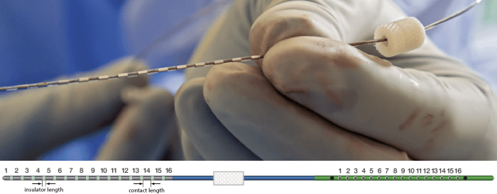
The depth electrodes used in this example dataset are PMT SEEG Depth Electrodes, with the following specifications:
- Diameter: 0.8 mm
- Contact length: 2 mm
- Insulator length: 1.5 mm
- Distance between the center of two contacts: 3.5 mm
- Between 8 and 16 contacts on each electrode
Files
tutorial_seeg_implantation/
preMRI.nii: MRI before the implantation of the sEEG.
postCT.nii: CT after the implantation of the sEEG.
All the anatomical images have been de-identified with defacing from BrainStorm.
Download and installation
Requirements: You have already followed all the introduction tutorials and you have a working copy of Brainstorm installed on your computer.
BrainSuite: Make sure you have the latest version of BrainSuite installed. Follow steps as per Installation here. This is required to perform skull stripping when importing CT below in order to mask out regions outside the skull.
SPM: If you are running Brainstorm from the MATLAB environment, you need to have the SPM12 toolbox installed on your computer, as a Brainstorm plugin or a custom installation.
With the stand-alone compiled version of Brainstorm: all the needed SPM scripts have been compiled and included in the executable.ct2mrireg: If you are running Brainstorm from the MATLAB environment, for the coregistration between pre-implantation MRI and post-implantation CT volumes, you need to have the ct2mrireg plugin installed on your computer, as a Brainstorm plugin. It can be found under the menu Plugins > Anatomy > ct2mrireg.
Download the dataset:
Go to the Download page of this website, and download the file: tutorial_seeg_implantation.zip.
- Unzip it in a folder that is not in any of the Brainstorm folders (program folder or database folder).
Brainstorm:
- Start Brainstorm (MATLAB scripts or stand-alone version).
Select the menu File > Create new protocol. Name it "TutorialSeegImplantation" and select the options:
"No, use individual anatomy",
"No, use one channel file per acquisition run".
Import the anatomy
Pre-implantation MRI
Right-click on the TutorialSeegImplantation folder > New subject > Subject01.
Keep the default options you defined for the protocol.Switch to the Anatomy view of the protocol.
Right-click on the subject node > Import MRI.
Set the file format: "All MRI file (subject space)".
Select: tutorial_seeg_implantation/preMRI.niiDo you want to apply the transformation to the MRI file? Yes
The MRI viewer opens automatically. Click on "Click here to compute MNI normalization", option "maff8". This method is embedded in Brainstorm and does not require the installation of SPM12. However, it requires the automatic download of the file SPM12 Tissue Probability Maps. If you do not have access to internet, see the instructions on the Installation page. It is based on an affine co-registration with the MNI ICBM152 template from the SPM software, described in the following article: Ashburner J, Friston KJ, Unified segmentation, NeuroImage 2005..
![[ATTACH]](/moin_static1911/brainstorm1/img/attach.png "[ATTACH]")
Click on Save to close the MRI viewer.
Rename the new file: preMRI.
Post-implantation CT
- The pre-implantation MRI will be used as the anatomical reference for this subject. We will now import a second scan done after the SEEG implantation, on which we can see the SEEG contacts. In this dataset, the post-implantation volume is a CT scan (contacts hypersignal appear in white).
Right-click on the subject node > Import CT.
Select: tutorial_seeg_implantation/postCT.niiChoose Yes/No for the Nifti Scaling depending on the requirement (here we choose No) and Yes for the transformation for MRI orientation.
Choose CT2MRI and Yes for reslicing so that we can overlay the CT with the MRI.
Choose if you want to remove regions outside of the skull. Here, we select Yes as we are just concerned with the electrodes inside the skull. It uses BrainSuite's skull stripping to mask out regions outside the skull. Make sure you follow the Installation instructions prior to running this step.
The MRI viewer opens automatically, showing the post-implantation CT volume as a colored layer on top of the previous volume. Adjust the transparency and amplitude threshold of this layer in the section Data options of the Surface tab, adjust its colormap with the popup menu of the figure. Use this display to validate that the coregistration of the two volume is correct, all the parts of the head must align well.
Rename the new file: postCT.
Generate isoSurface
This creates a thresholded mesh from the CT to separate the contacts out from rest of the CT. This aids the user towards localization of the electrodes and its contacts more accurately.
Right click on postCT > CT segmentation > Generate threshold mesh from CT.
This will bring the Generate isosurface window. This window shows 4 things in Hounsfield Unit (HU) i.e. the Background level, the White level, the Max Intensity and the Set isoValue field. The first 3 values are calculated automatically from the histogram of the CT and is displayed for reference. This is to help the user to decide on what to set the isoValue for getting a good thresholded mesh. Another way is to refer to the Wiki. The editable isoValue field shows an estimated best guess based on mean of White Level and Max Intensity. Just let that value be and press OK.
An isosurface is generated showing the contact as blobs overlayed on the 3D MRI slices. The Thresh slider under Surface options can be used to fine tune and regenerate mesh with different isoValues.
Electrode labelling and contact localization
Get started
Right click on postCT, and choose SEEG/ECOG implantation. This takes you to the functional tab and Subject01 > Implantation > SEEG/ECOG (0) channel gets created. Also the MRI Viewer with the CT loaded and 3D Viz with the isoSurface+3D MRI Slices loaded opens up along with the Panel iEEG. Move around the 3D slices to get a clear view of the contacts so that they can be clicked on. This section explains the controls.
Panel iEEG
When opening SEEG/ECOG recordings, the panel iEEG is added to the Brainstorm window. You can use it to edit the display properties of the depth electrodes. In this interface, "electrode" refers to entire depth electrode implanted in the head of the patient while "contact" refers to recording sites on the electrode. There are multiple contacts on an electrode, and one contact corresponds to one channel of data in the channel file and the recordings.
SEEG depth electrodes are graphical objects, they are defined independently from the SEEG contacts available in the channel file and recordings. A contact/channel is associated to a depth electrode using the Group property of the channel, accessible with a right-click on the channel file > Edit channel file.
In this example, the depth electrodes available in the Panel iEEG have been manually set by using this Panel features. In the convention used here, the contact names must start with one or more letters (the name of the electrode) followed by a number representing the index of the contact on the electrode. Contact #1 is at the tip of the electrode, and is therefore the deeper contact of the electrode. If the convention used in your recordings is different, you may have to edit the electrodes properties in order to get them displayed correctly.
- Buttons in the toolbar:
Coordinates (millimeters) radio buttons: Users can switch between the different coordinate systems (SCS, MRI, World, MNI) to change the coordinate values of the contacts.
- (Add new electrode): Adds an entry for a new depth electrode. The new electrode will not be displayed until you set its properties and position. This will not add or remove SEEG contacts or channels of data.
- (Remove selected electrodes): Deletes a depth electrode from the list, but does not modify the list of SEEG contacts or channels of data.
- (Select surface point): Activates coordinate selection in 3D figure window. (Shortcut: Ctrl+P)
- (Set color for selected electrodes): Self explanatory.
- (Show/hide selected electrodes): To hide an electrode in the 3D figures and MRI viewer, select it in the list then click on this button. Select all the electrodes with the standard shortcut Ctrl+A.
Display contacts as:
(Depth electrodes) / (Spheres). Contacts > Set default positions: For each of the selected electrodes, the current positions of the SEEG contacts are discarded and replaced with the default positions of the contacts on the electrode. The properties used for setting the position of the contacts are the contact spacing, the tip of the electrode and the entry point in the skull. Contact #i is placed along the electrode at (i-1)*contact_spacing millimeters from the tip of the electrode.
Contacts > Project on electrode: For each of the selected electrodes, the contacts are projected orthogonally on the electrode. This menu can be useful for aligning contacts that were marked one by one.
Contacts > Show/Hide line fit through contacts: Performs line fitting through the contacts in 3D figure.
Contacts > Save modifications: Save the current modifications to the channel file. Otherwise, the modifications are saved only when you close the figure (dialog box "Save modifications to channel file?")
Contacts > Export contacts positions: Save the 3D positions of the SEEG contacts in a text file, using one of the file formats supported by Brainstorm.
Electrode properties: Properties that have an impact on the position of the contacts.
- If you edit the properties, the modifications will apply to all the selected electrodes in the current channel file. Check what is selected before making changes.
Type: SEEG/ECOG
Model: List of electrode models. If you select an entry in this menu, it will copy the default properties for this model to the selected electrodes. If you are using electrodes that are not in this list, please post on the specification of your devices on the user forum and we will add them to this list.
Number of contacts: Number of recording sites on the electrode. By default, this is set for SEEG to the maximum index found in a group of contacts. Example: electrode s' is associated to channels s'1, s'2, s'3, s'10, s'11, s'12 => detected number of contacts is 12.
Contact spacing: Distance between the centers of two consecutive contacts in the electrode. In this example dataset, the default value corresponds to the average distance observed between pairs of adjacent contacts.
Set tip: Select one electrode in the list, then move the cursor of the MRI viewer to the tip of the selected electrode (center of the first contact) or choose the contact from the isoSurface in the 3D Viz and finally click on [Set tip].
Set skull entry: Select one electrode in the list, then move the cursor of the MRI viewer to the point where the depth electrode enters the skull or choose the point from the isoSurface in the 3D Viz, and finally click on [Set skull entry]. This position does not actually correspond to any contact, it is used only to estimate the direction of the depth electrode. More details.
- Display options: Properties that only affect the way the electrodes are renderer graphically.
Contact length: Defines the length of the yellow cylinder that represents the contacts along the electrode axis, or the diameter of the sphere when the electrodes are not rendered.
Contact diameter: Diameter of the yellow cylinders representing the contacts. By default, this value is slightly larger than the electrode diameter so that it is rendered correctly. If you use the same value as the electrode diameter, the contacts might not be visible.
Electrode diameter: Diameter of the cylinder representing the SEEG depth electrode.
Electrode length: Length of the cylinder representing the SEEG depth electrode.
Create electrodes and plot contacts manually
After performing steps as per Get Started, we will have the Panel iEEG along with the MRI Viewer and 3D Viz open.
On Panel iEEG Click on the + (Add new electrode). This opens up the Add electrode window. Enter anything under Electrode label based on your convention. For this e.g., enter A and press OK.
This creates an electrode A in selected state, and at the bottom the Electrode configuration section of the panel becomes active. Select the following:
Model: Choose PMT 2102-16-091/2102-16-101 from the drop down list. This will automatically set the other parameters in the section. More details for these parameters can be found in the advanced section here.
Set tip: Click the ![]() button (shortcut: Ctrl+P) and choose the contact (deepest contact) for the electrode in the isosurface in 3D Viz which is going to be set as the tip. This should plot a yellow crosshair marker point on the blob and also update the MRI Viewer's crosshair. At the bottom in Panel iEEG click Set tip and the button turns green indicating that the tip has been set. This point in 3D is at the centroid of the blob which gives a more accurate location of the contact compared to the same if chosen from the MRI.
button (shortcut: Ctrl+P) and choose the contact (deepest contact) for the electrode in the isosurface in 3D Viz which is going to be set as the tip. This should plot a yellow crosshair marker point on the blob and also update the MRI Viewer's crosshair. At the bottom in Panel iEEG click Set tip and the button turns green indicating that the tip has been set. This point in 3D is at the centroid of the blob which gives a more accurate location of the contact compared to the same if chosen from the MRI.
Note: You can play around with the "Thresh" slider as mentioned here to get better visibility of the contacts as required Click on When you are done with everything, click on
Until now, the electrode is always assumed to follow a straight path but practically that is not the case as there could be bending introduced when the neurosurgeon inserts the electrode. In such cases we need to move most of the intermediate contacts to more appropriate positions. Let's take the case of a curved electrode. You can toggle between the electrode and sphere views to get the figures as under using buttons in Panel iEEG. Keep it in the sphere mode for better visibility. The contacts definitely need to be corrected and moved to their right positions. Click on the individual contacts (in green) in the 3D Viz and it highlights the corresponding location in MRI Viewer and also the panel. You can display the contact labels in 3D Viz by right clicking From the above it is clear that contacts beyond In the MRI Viewer, right click and go to This updates the position of contact Double click on the Follow the above steps to update all the remaining contacts as required.
![]()
![]()
Set skull entry: Choose the point in the isosurface in 3D Viz which is going to be set as the skull entry. This point can be any of the contacts other than the tip preferably closer to the skull so that we get an orientation of the electrode. This should plot a yellow crosshair marker point on the blob and also update the MRI Viewer's crosshair. At the bottom in Panel iEEG click Set skull entry and the button turns green indicating that the entry point has been set. The properties used for setting the position of the contacts are the contact spacing, the tip of the electrode and the entry point in the skull. Contact #i is placed along the electrode at (i-1)*contact_spacing millimeters from the tip of the electrode. The MRI Viewer gets updated with the an electrode based on the above configuration. Some more fine tuning may be required and user might need to edit the individual contacts. This section explains it in details. Note: You can play around with the "Thresh" slider as mentioned here to get better visibility of the contacts as required
![]()
Contacts > Save Modifications to update the channel information.
![]()
![]()
Edit contact positions
![]()
Channels > Display labels.
![]()
![]()
![]()
![]()
![]()
![]()
Walkthrough Video
Additional documentation
Related tutorials