|
Size: 28662
Comment:
|
Size: 28757
Comment:
|
| Deletions are marked like this. | Additions are marked like this. |
| Line 269: | Line 269: |
<<EmbedContent(http://neuroimage.usc.edu/bst/get_feedback.php?seeg/SeizureFingerprinting)>> |
SEEG Time-Frequency Fingerprint Analysis for Epileptogenic Zone Localization
Authors: Yash Shashank Vakilna, Chinmay Chinara, Johnson Hampson, Takfarinas Medani, Raymundo Cassani, John Mosher, Sylvain Baillet, Richard Leahy
TODO: Add flowchart
It guides users through computing time-frequency decomposition maps to identify the epileptogenic zone (EZ) using both ictal and interictal SEEG data.
Contents
Access the recordings
Link the recordings
- Switch to the "functional data" view (2nd button, on top of the database explorer).
Right-click on the subject folder > Review raw file:
Select the file format: EEG: EDF/EDF+
Select all the recordings: tutorial_seizure_fingerprinting/recordings/*.edf

The selected recordings get added to the database.
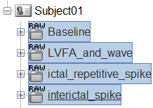
The new files Link to raw file let you access directly the contents of the original SEEG files. The menu Review raw file does not actually copy any data to the database. More details.
Import the contacts positions
In order to generate epileptogenicity maps, we need accurate 3D positions for the contacts of the depth electrodes. Placing the contacts requires a good understanding of the implantation scheme reported by the neurosurgeon, and some skills in reading MRI scans.
- The channel file "EDF channels" contain the name of the channels, but not their positions. We need to import or edit separately the positions of the SEEG contacts.
Click on the [+] next to the four folders, select all the channel files simultaneously.
Right-click one channel file > Add EEG positions > From other studies > Implantation
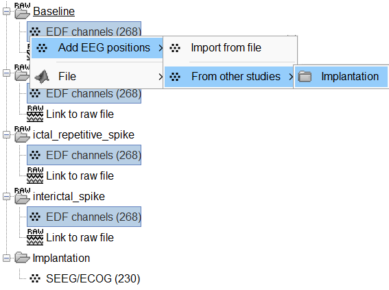
At the end, you get a report indicating how many channels from the SEEG recordings were attributed a new 3D position. The channels are matched by name: the position file you import must include the labels of the channels and they must be named exactly in the the same way as in your recordings.
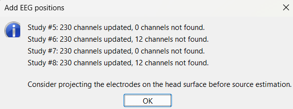
For EDF Channels under LVFA_and_wave and interictal_spike, there were 12 channels not found. The type of the channels for which a position was not found is set to EEG_NO_LOC, in order to ignore them when processing the SEEG data. In this example dataset, the channels numbered 245 to 255 and 262 are not found as they are not SEEG contacts.
For all the EDF Channels, mark the channel MPS16 as SEEG_NO_LOC because if not marked, when we compute the forward head model using BEM surfaces it says that MPS16 lies outside the BEM layer. Marking it excludes it from any future computations.
You should always validate that the type of all the channels has been detected correctly. Check also that the names are correct and using the same convention for all the contact of a given electrode. These are entered manually, and typing errors are frequent. Right-click on a channel file > Edit channel file.

To edit one channel, double-click on the text to modify. To edit multiple channels, select them all and right-click > Set channel group/type. The column Group corresponds to the name of the depth electrode. It is detected based on the channel type and name. If you include as SEEG a channel that detected as something else or rename a channel, you would need to manually update the channel name.
If you don't have the positions for the SEEG contacts, or if they don't look correctly aligned, see the section Edit the contacts positions on how to tackle it.
To make this tutorial easier to reproduce and follow, we also distribute the positions of the contacts (that were localized as per the section above) exported as a .tsv file (tutorial_seizure_fingerprinting/recordings/Subject01_electrodes_mm.tsv). To import the contacts position from that refer to Epileptogenicity tutorial.
Display the depth electrodes
3D figures
Right-click on the channel file > Display sensors and explore all the available options.
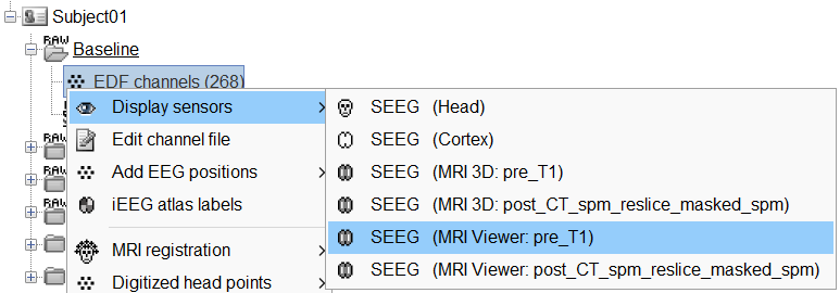
You can render the SEEG depth electrodes in 3D together with the subject anatomy: surfaces, pre- or post-implantation volumes. You can add more anatomy elements to the figure with the button Add a surface (
![[ATTACH] [ATTACH]](/moin_static1911/brainstorm1/img/attach.png) ) at the top-right of the Surface tab. For more help: Display the anatomy.
) at the top-right of the Surface tab. For more help: Display the anatomy.
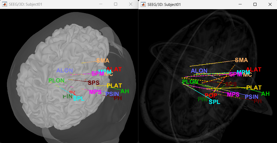
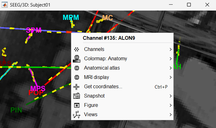
Click on a contact to select it, right-click on it to get its name.
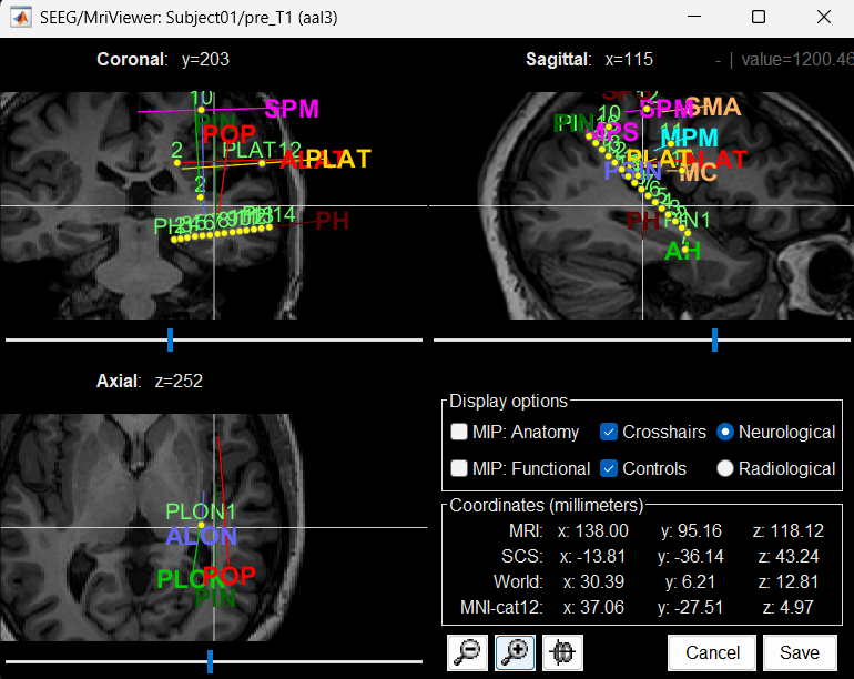
MRI Viewer
You can also display the contacts in the MRI viewer, on top of the the pre- or post-implantation volumes. By default, the electrode is displayed in a slice if there is a SEEG contact associated to it in the slice.
To display all the electrodes, select the option "MIP: Functional". For a glass-brain view, select at the same time the option "MIP: Anatomy".
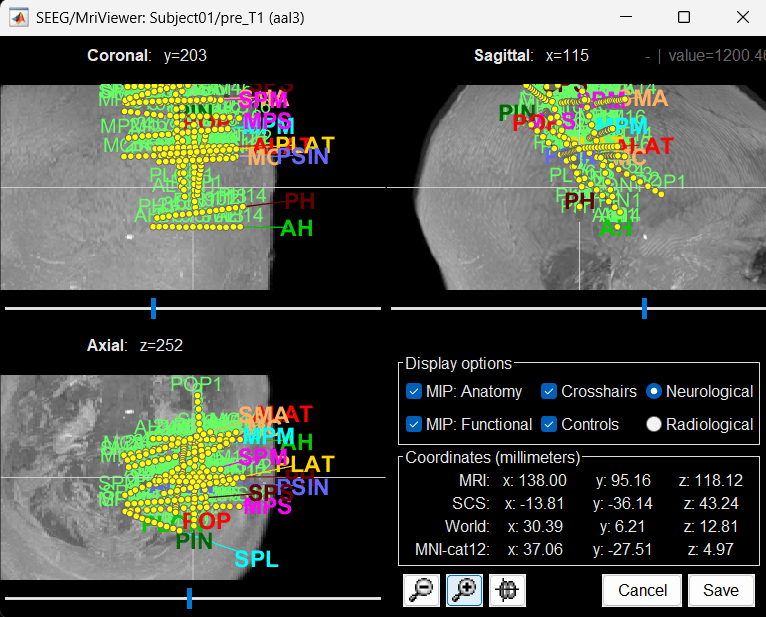
Zoom in/out with the buttons or the associated shortcuts (Ctrl+Scroll or +/-) and explore the volume with (Shift+)x/y/z. Additional display options are available in the popup menu for this figure. All the shortcuts are listed in this tutorial.
Panel iEEG
When opening SEEG/ECOG recordings, the panel iEEG is added to the Brainstorm window. You can use it to edit the display properties of the depth electrodes. More details about the iEEG Panel can be found in the Epileptogenicity tutorial.
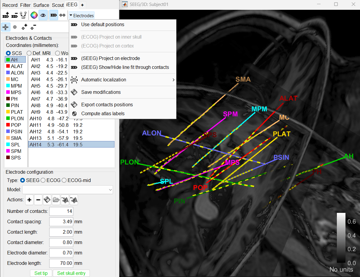
To know more about ways to display the SEEG recordings in Brainstorm refer to the Epileptogenicity tutorial.
Review recordings
Power spectrum
We recommend that you start your data analysis with a power spectral density estimation of the recordings to check the quality of sensor recording. This is described in more details in the Power spectrum tutorial.
In Process1, select all the continuous files (Link to raw files or folders).
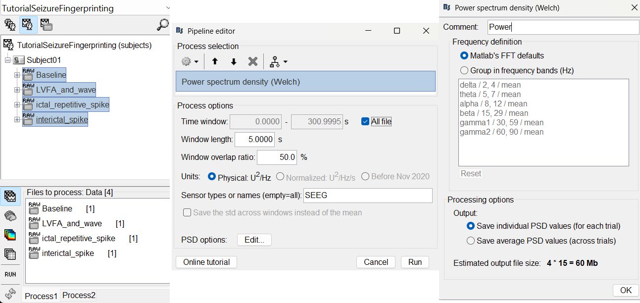
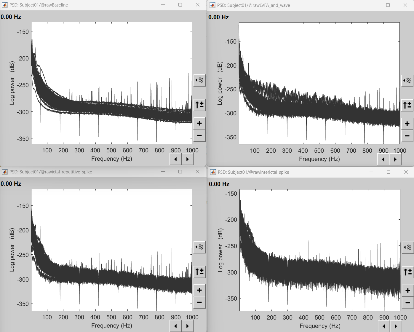
Double-click on the PSD files to display them. It can be seen that the power line interference at 60Hz along with its harmonics have been removed. This was done using a notch filter. More details can be found in the notch filter section in the above tutorial.
Add events
We need to mark seizure onset event for the ictal and LVFA and wave recordings and spike event for interictal recording. There are events already available in recordings, that were marked for clinical use, to jump quickly to the page of interest. More details can be found in the tutorial Event Markers.
For LVFA and wave, we will create a new event sEEG Onset at around 15s (center of the 30s recording extract).
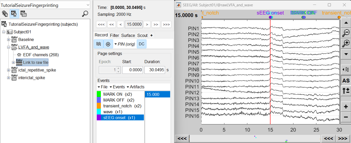
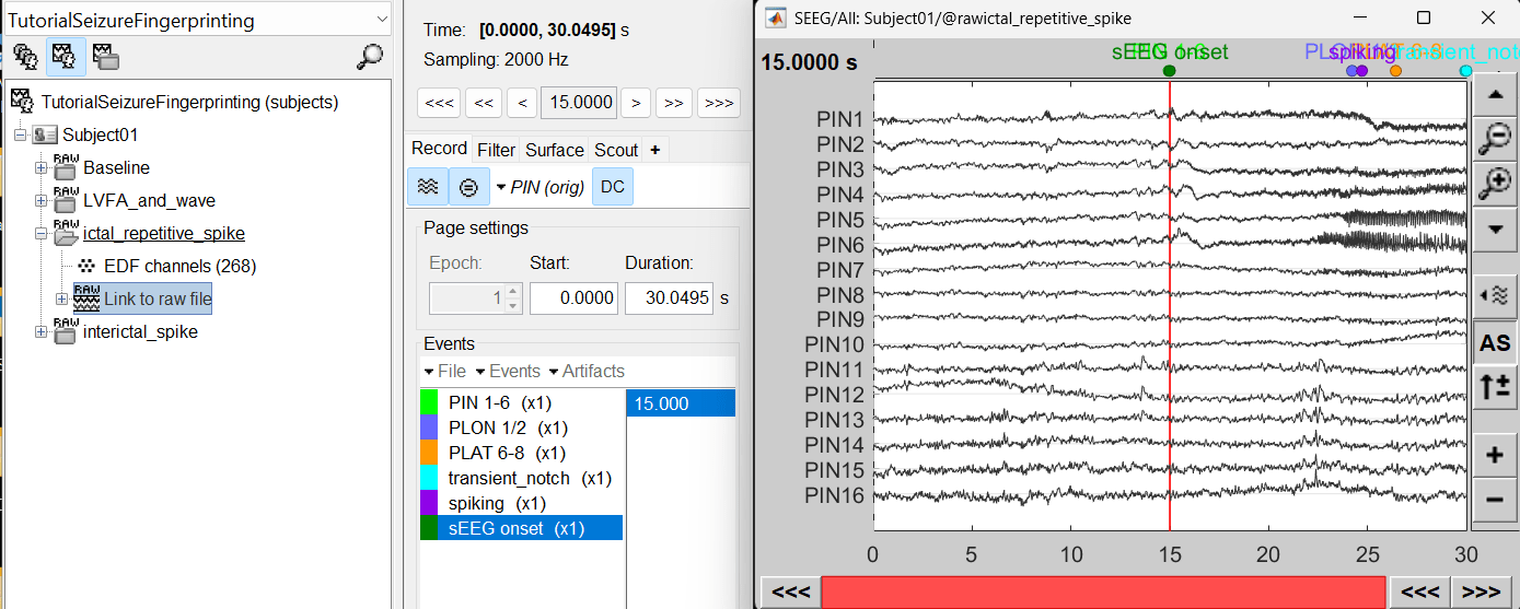
For ictal repetitive spike, we will create a new event sEEG Onset at around 15s (center of the 30s recording extract).
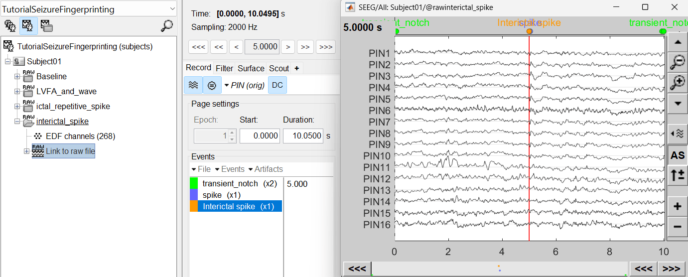
For interictal spike, we will create a new event Interictal spike at around 5s (center of the 10s recording extract).
Import epochs of interest
At this point of the analysis, we are still looking at the original files, no SEEG data was copied to the database. The montages are saved in the Brainstorm preferences, the new events are saved in the links of the database.
We are now going to import the three segment of recordings i.e. LVFA and wave , ictal repetitive spike and interictal spike which are a subset of the Baseline recording.
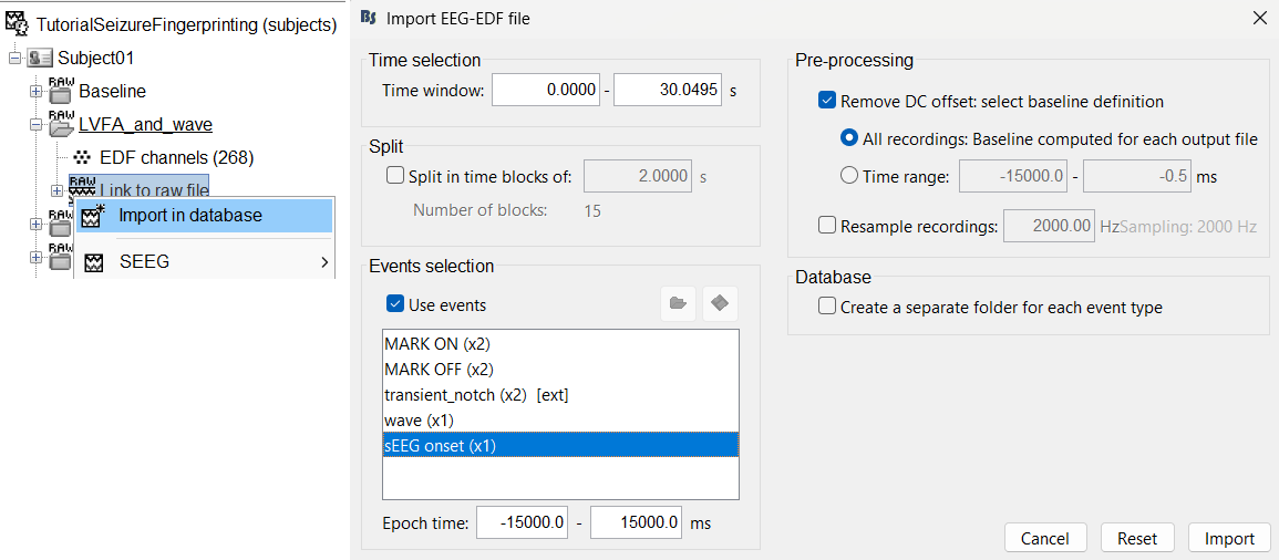
Import in database
Right click on LVFA_and_wave > Link to raw file > Import in database.
- Time window: All (0 to 30.0495)
- Split in time blocks: Disabled
Use events: Enabled, select sEEG Onset
Epoch time: [-15000, +15000] ms (imports -15s to 15s around the event sEEG Onset)
Remove DC offset: Enabled. More details can be found here.
- Resample: Disabled
- Create a separate folder for each event type: Disabled
Click Import.
Repeat the same steps above for importing ictal repetitive spike into the database.
Repeat the same steps above for importing interictal spike into the database with the modification in the following options:
- Time window: All (0 to 10.0495)
Use events: Enabled, select Interictal spike
Epoch time: [-5000, +5000] ms (imports -5s to 5s around the event Interictal spike)
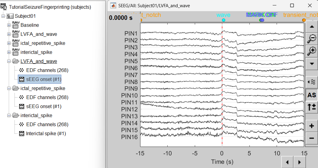
At the end, you should have three new folders LVFA and wave , ictal repetitive spike and interictal spike, the same name as the original raw files, but without the tag RAW on top. These new folders contain copies of the SEEG recordings, if you delete these folders from the database explorer, you lose the recordings they contain.
The imported epochs are saved with a new timing: for LVFA and wave and ictal repetitive spike, the reference time t=0s is now the event sEEG Onset and for Interictal spike, the reference time t=0s is now the event Interictal spike, which has been removed from the list. You can still see the other marker timings adjusted accordingly.
Bipolar montage
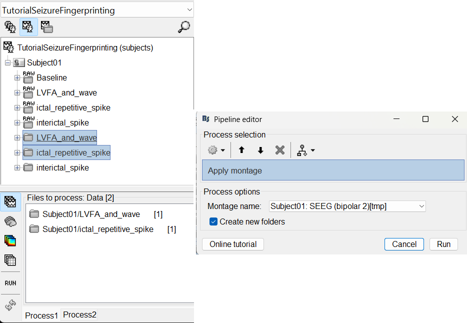
We will run the rest of the analysis using a bipolar montage (bipolar-2). The montage selected in the Record tab is for visualization only, most processes ignore this selection and work only on the original common-referential montage. To compute bipolar montage on time series, we need to explicitly apply the montage to the recordings. More details can be found in tutorials Montage editor and Epileptogenicity.
In Process1, drag and drop all the imported recordings (either the folders or the files).
Run the process Standardize > Apply montage
Montage name: Subject01: SEEG (bipolar 2)[tmp]
Create new folders: Enabled
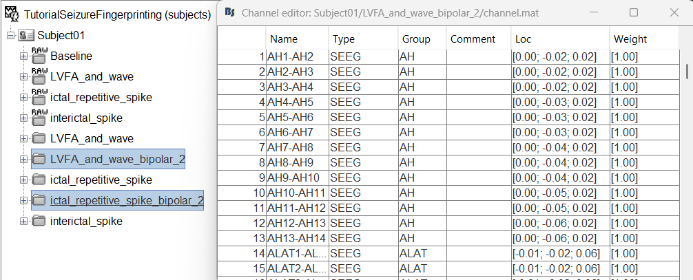
This process rewrites the channel files and data files in the selected folders. The position associated with a bipolar channel in the channel file is the middle of the segment between the two contacts (e.g. AH1-AH2 is placed half-way between AH1 and AH2).
Head modeling
The forward models depend on the subject's anatomy, including head size and geometry, tissue conductivity, the computational method, and sensor characteristics. In this section, we will use the Boundary Element Method (BEM) approach available in Brainstorm for constructing the head model for sEEG.
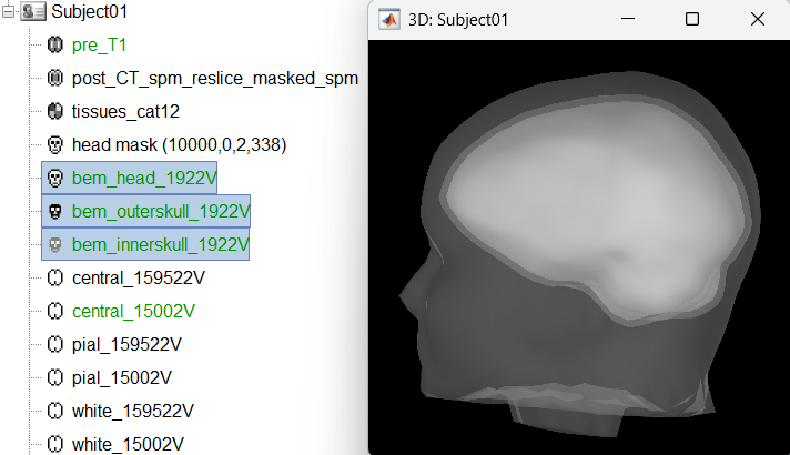
We will first generate the BEM head surfaces from the MRI. More details can be found in OpenMEEG BEM tutorial. This will generate three surfaces head, outer skull and inner skull estimated from the head mask and the cortex obtained from the segmentation. The BEM surfaces will be used for the BEM forward computation below.
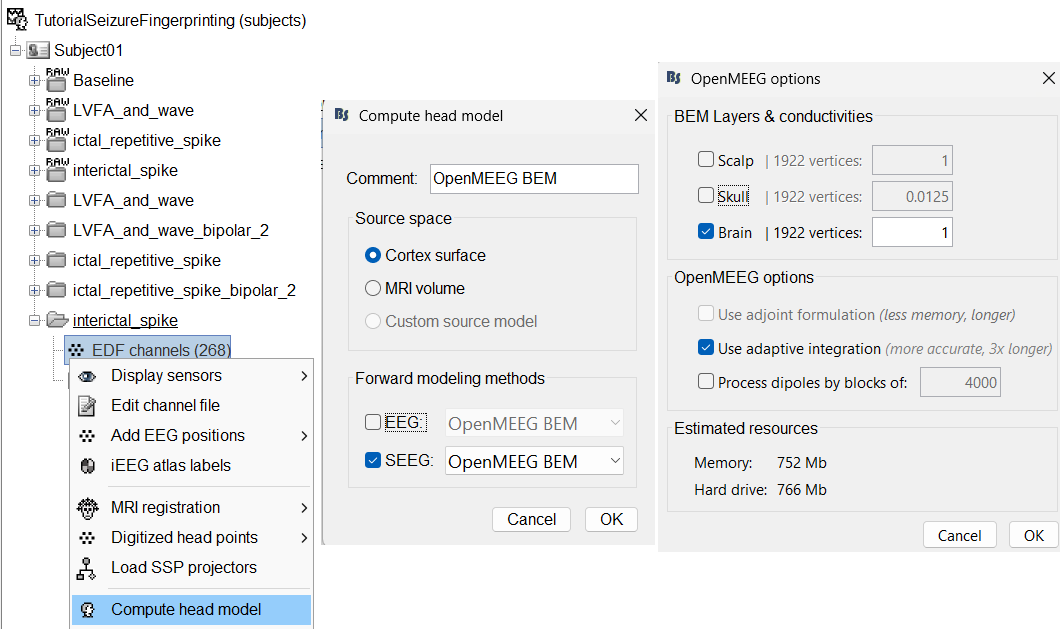
We will then compute the forward head model using the OpenMEEG BEM method. Switch to functional tab, right-click on the interictal_spike > EDF channels > Compute head model.
Source space: Cortex surface
Forward modelling methods: SEEG: OpenMEEG BEM
Use only Brain in BEM layers and conductivities (corresponds to bem_innerskull surface) as other surfaces do not matter for SEEG.
Use default OpenMEEG options.
A new head model will be added to the folder.
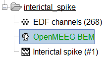
Right click on the head model file > Copy to other folders. Since the other folders contain data collected from the same subject using the same set of electrodes, we do not need to recompute the head model for each of them separately.
View leadfield vectors:
Right click on the head model file > View SEEG leadfield vectors
Select reference MC2 and click OK
Click on the figure and press E to display the electrodes
Make sure scouts are unselected (Scout tab > ALL and SEL unselected)
Surface tab: transparency = 90 and press Shift+Up arrow till the arrows are visible. Press Up/down to change the Reference electrode, Right/Left to change the target. Close all figures once done.
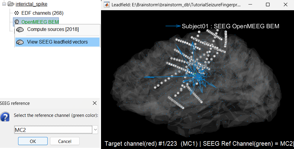
Compute noise covariance matrix
We will compute the noise covariance matrix for the Baseline recording as per the tutorial Noise covariance.
Right click on the Baseline (RAW) > Link to raw file > Noise covariance > Compute from recordings . Keep the default values and click OK.
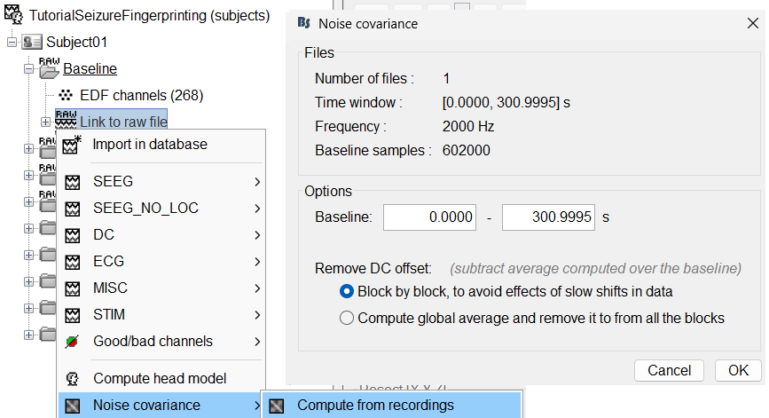
Noise covariance node gets added to the database.
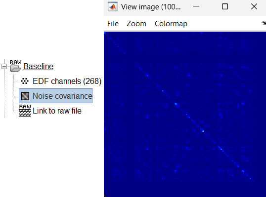
Right click on the Noise covariance and Copy to other folders.
Modeling interictal spikes
Compute inverse model
We will compute the inverse model for the interictal_spike recording. For more details refer to the tutorials Source estimation and Volume source estimation.
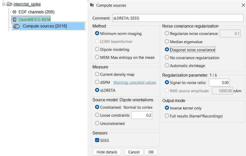
Expand the interictal_spike folder, right click on OpenMEEG BEM > Compute sources [2018].
Method: Minimum norm imaging
Measure: sLORETA
Source model: Dipole orientations: Constrained: Normal to cortex
Noise covariance regularization: Diagonal noise covariance
Regularization parameter: Signal-to-noise ratio: 3.00
- Output mode: Inverse kernel only
Sensors: SEEG. Click OK.
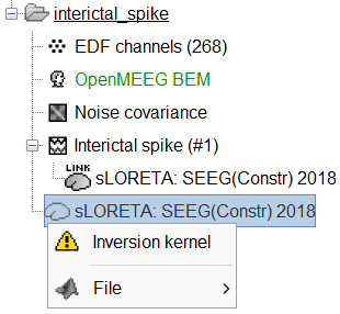
Two files get added to database. To learn about inversion kernel and LINK files in database refer to this section.
Display sensor time series
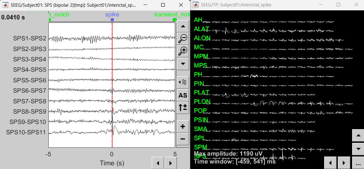
Display time series
Right-click on recording Interictal spike > SEEG > Display time series
On the Record tab, select montage SPS (bipolar 2)
Select the first peak of SPS10-SPS11 (Time 0.041s).
Display 2D layout of the spike
Right-click on recording Interictal spike > SEEG > 2D Layout
Click [...] on the corner and set[-500, 500] as the time window. Doing this will enable visualizing 1s of data across all the sensors giving a more clear sense of where the different spikes are.
View sources
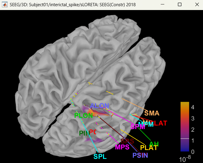
Display on cortex
Right click on sLORETA (LINK) > Cortical activations > Display on cortex
Show sensors: Ctrl+L (electrodes)
Set colormap: Colorbar > Colormap:Sources > Permanent menu, select Maximum: Global, Contrast -0, Brightness 0
Switch to Surface tab: Amplitude 26%, Min size 13
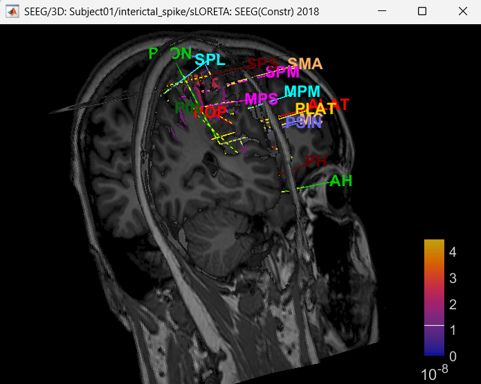
Display on 3D MRI viewer
Right click on sLORETA (LINK) > Cortical activations > Display on MRI (3D)
Show sensors: Ctrl+L (electrodes)
Press M to go to voxel with maximum intensity
Display on MRI viewer
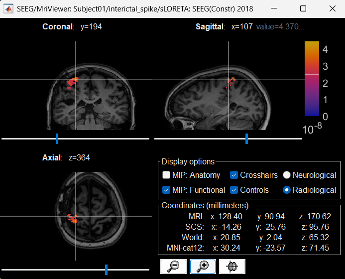
Right click on sLORETA (LINK) > Cortical activations > Display on MRI (MRI Viewer)
Turn on MIP: Functional
Switch to Surface tab, Amplitude: 56%, and press M to select voxel with maximum intensity
Atlases and scouts
- Display sources on the cortical surface
Right click on sLORETA (LINK) > Cortical activations > Display on Cortex
In the Scout tab, use the drop box to select Desikan-Killiany and click on ALL. This atlas is provided by default in Brainstorm. Ctrl+L to show all electrodes.
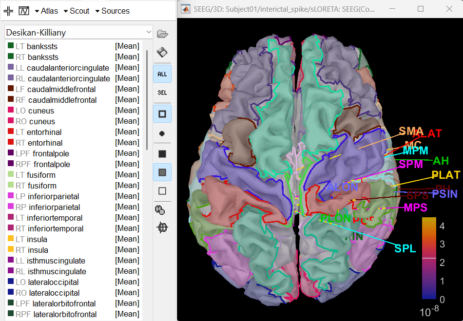
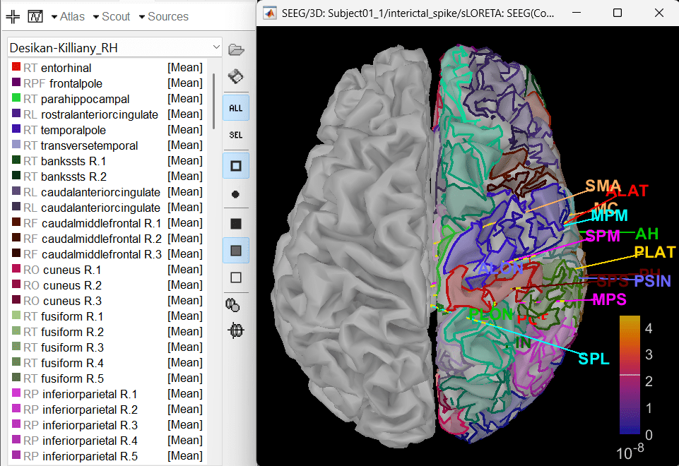
- Since all the electrodes in the data are implanted on the right hemisphere of the brain, it is better to edit this atlas to only have scouts defined for the right region and remove the rest. Also we can subdivide the atlas to smaller scout regions to have smaller ROIs that will help in having better and more focused time-frequency epileptogenic maps later in the tutorial.
In Scout tab, select all the scouts in the right hemisphere and then create a new atlas from the selected scouts by Atlas > New atlas > Copy selected scouts. It will create a new atlas named Desikan-Killiany_02. Rename it to Desikan-Killiany_RH where "RH" indicates right hemisphere.
Atlas > Subdivide atlas > Area > Area of the sub-regions: 5 (cm sq.). A total of 176 scouts will be created with smaller and more focused ROI.
To know more about scouts in Brainstorm refer to the tutorial Scouts.
Modeling ictal wave
Switch to the folder LVFA_and_wave (not the RAW folder) and repeat the steps to compute inverse model as per the section above and study the sensor time series and inverse modeling results.
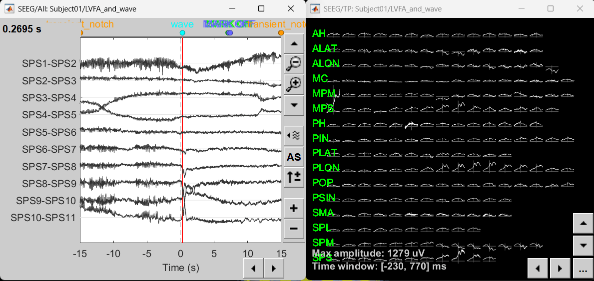

Modeling ictal onset with LVFA
Sensor space
Compute time-frequency decomposition
Navigate and expand LVFA_and_wave_bipolar_2 folder
Delete any previous recordings in the Process 1 tab below
Drag-and-drop recording file sEEG onset (#1) | bipolar 2 in Process 1, click [RUN]
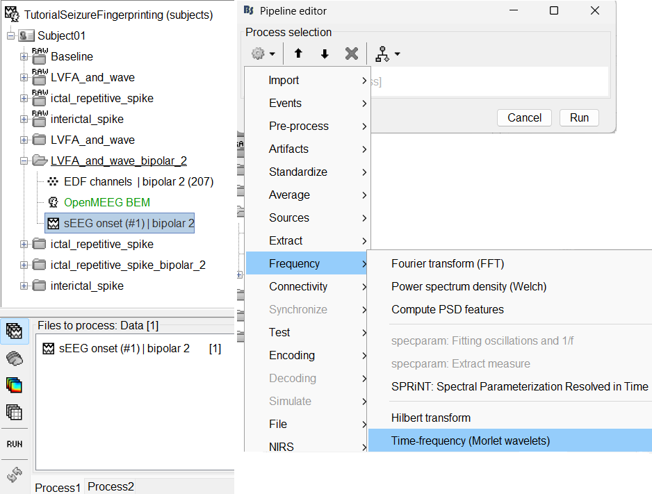
Add the process: Frequency > Time-frequency (Morlet wavelets)
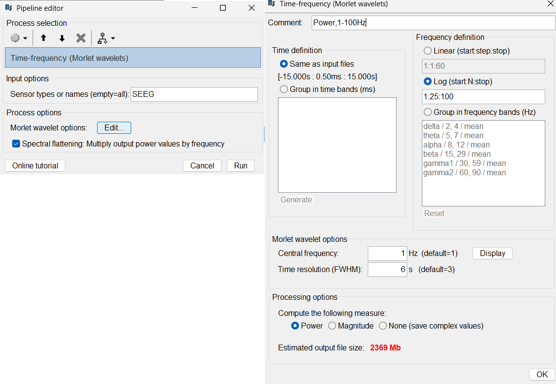
Sensor type: SEEG
Select Spectral flattening: Multiply output power values by frequency
Click Edit...
Frequency definition: Log (start:N:stop), 1:25:100
Central Frequency: 1 Hz, Time resolution (FWHM): 6s. Click OK and Run.
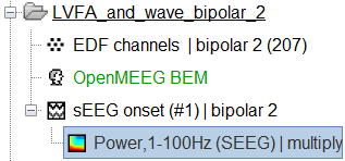
A new node Power,1-100Hz (SEEG) | multiply gets added to the database.
For more details go through the tutorial Time-frequency.
View time-frequency maps
Right click sEEG onset (#1) | bipolar 2 > Power,1-100Hz (SEEG) | multiply > All channels
Click on Log(Power) to bring out the essential features in the maps.
Click on Smooth display to apply a Gaussian kernel to the map so that the underlying pattern becomes clearer for viewing.
Click on SPS8-SPS9
Set colormap: right-click on Colorbar > Colormap: Timefreq > Permanent menu, Turn-off [Absolute Value](if on), Maximum: Local, Contrast 49 Brightness -65
Right-click on the colored time-frequency plot > Power Spectrum, Time Series
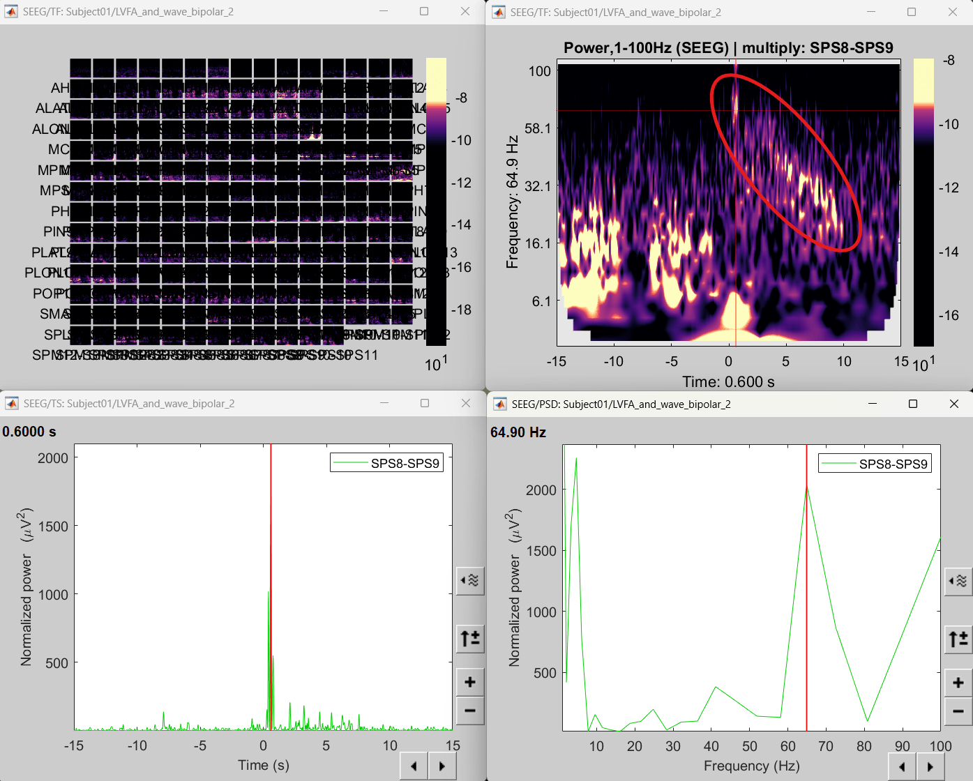
- The red marked area above is the high frequency activity. The bottom right area contains the pre-ictal spikes that is signature of seizure fingerprinting.
Source space
Extract scout time series
- We are going to now extract a single time-series for each of these scouts that best defines it.
Switch to the folder LVFA_and_wave (not the RAW folder).
Drag-and-drop sLORETA: SEEG(Constr) 2018 (LINK) in Process 1, click [RUN]
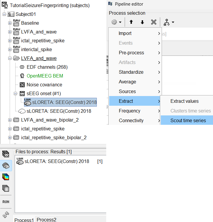
Add the process: Extract > Scout time series
Select Desikan-Killiany_RH.
Select scouts: Press Ctrl+A to select all the scouts in the box.
Select Scout function: PCA
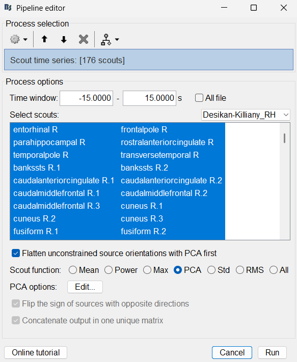
A new matrix file sEEG onset (#1) | 176 scouts gets added to the database.
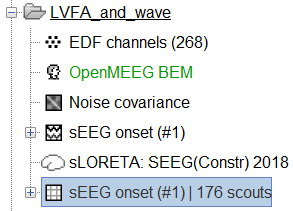
Right click on matrix file sEEG onset (#1) | 176 scouts > Display as time series.
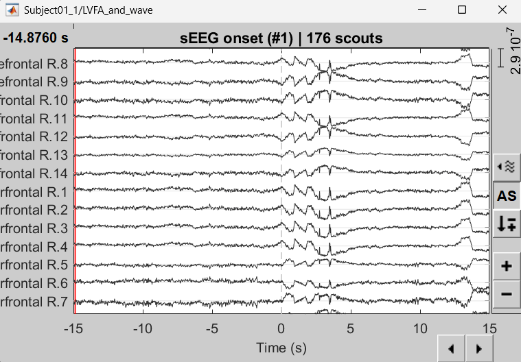
Compute time-frequency decomposition
Drag-and-drop matrix file sEEG onset (#1) | 176 scouts in Process 1, click [RUN]
Rest of the steps are the same as the corresponding earlier section in sensor space.
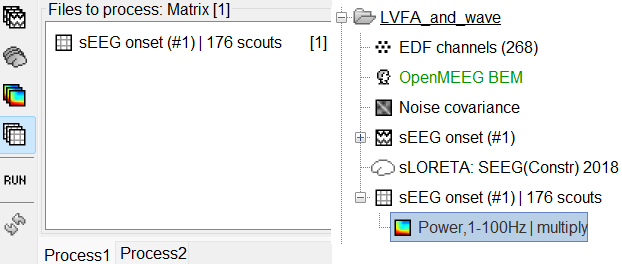
View time-frequency maps
Right click on matrix file sEEG onset (#1) | 176 scouts > Power,1-100Hz | multiply > Time-freq: All matrices
Right click on matrix file sEEG onset (#1) | 176 scouts > Power,1-100Hz | multiply > Time-freq: One matrix. Set selected data as postcentral R.3.
Click on Log(Power), Smooth display.
Set colormap: right-click on Colorbar > Colormap: Timefreq > Permanent menu, Turn-off [Absolute Value](if on), Maximum: Local, Contrast 52 Brightness -63
Right-click on the colored time-frequency plot > Power Spectrum, Time Series
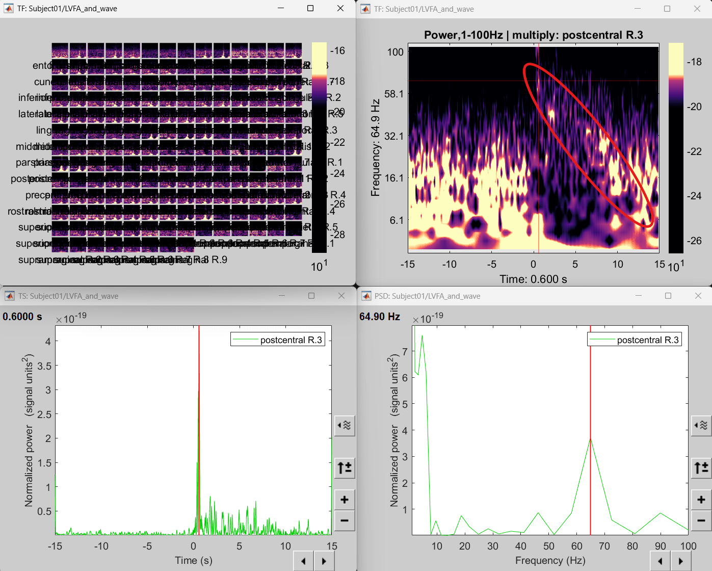
The red marked area above is the high frequency activity. The bottom right area contains the pre-ictal spikes that is signature of seizure fingerprinting. We can say that this patch of cortex postcentral R.3 was most associated with the LVFA pattern.
Modeling ictal onset with repetitive spiking
Sensor space
Display time-series
Expand the folder ictal_repetitive_spike_bipolar_2
Right click on sEEG onset (#1) | bipolar 2 > Display time series
Change Montage to PIN > PIN (orig)
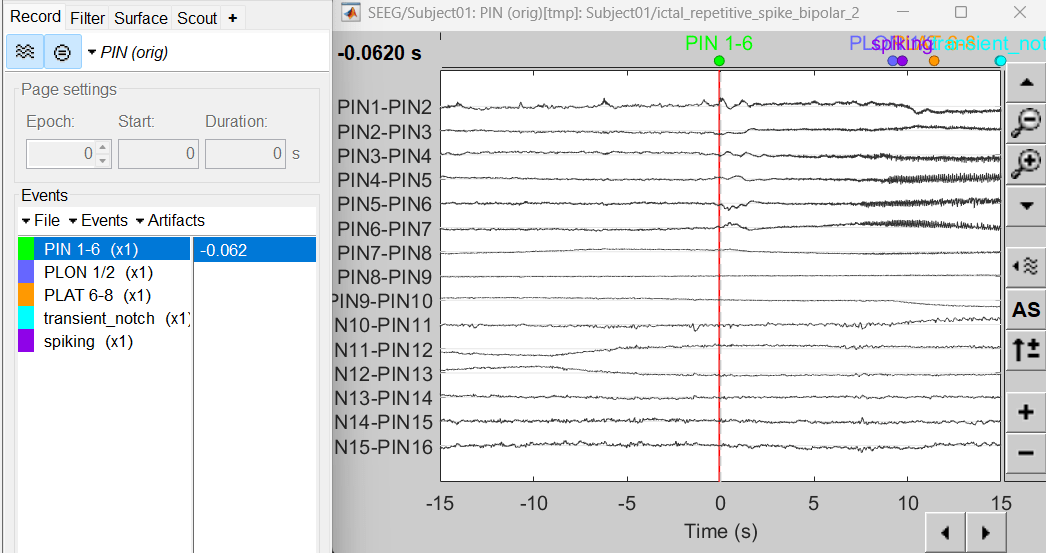
Compute time-frequency decomposition
Same as above sections. Only one change, set sensor type: PIN5-PIN6 for Time-frequency (Morlet wavelets) process.
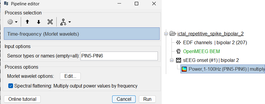
View time-frequency maps
Right click on file sEEG onset (#1) | bipolar 2 > Power,1-100Hz (PIN5-PIN6) | multiply > One channel.
Click on Log(Power), Smooth display.
Set colormap: right-click on Colorbar > Colormap: Timefreq > Permanent menu, Maximum: local, Contrast 23 Brightness -60
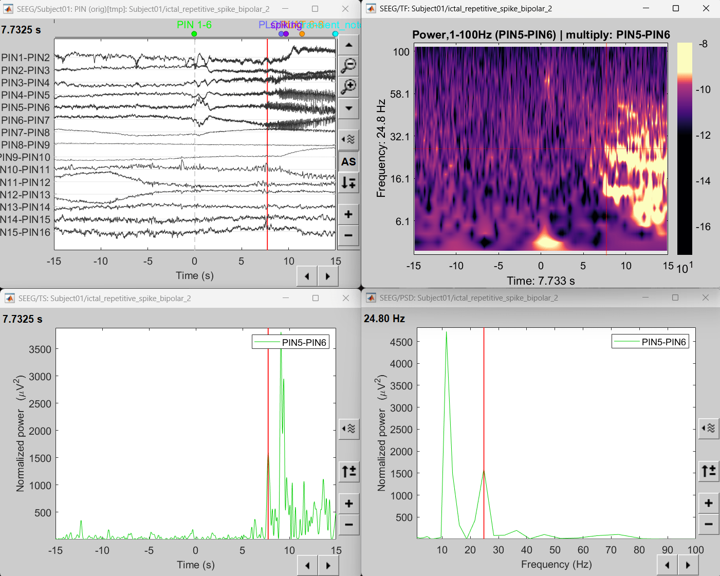
- The high frequency activity on the right is due to the rhythmic activity seen in the time series for PIN5-PIN6. On analyzing the time-frequency map, this activity is localized between 5Hz and 55Hz. So we need to filter this frequency range so that our results are more focused on the rhythmic activity.
Source space
Compute inverse model
Switch to the folder ictal_repetitive_spike
Repeat the steps as in the previous section.
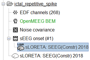
View sources
Right-click on sEEG onset (#1) > SEEG > Display time series.
Change Montage to PIN(orig)
Set frequency filter: High-pass: 5Hz, Low-pass: 55Hz
Display sources on MRI viewer
Right-click on sLORETA: SEEG(Constr) 2018 (LINK) > Cortical activations > Display on MRI (MRI Viewer)
Set colormap: Right Click on Colorbar > Colormap: Sources > Permanent Menu, Maximum: Custom [0, 2]
Click on Surface tab, set Amplitude 33%
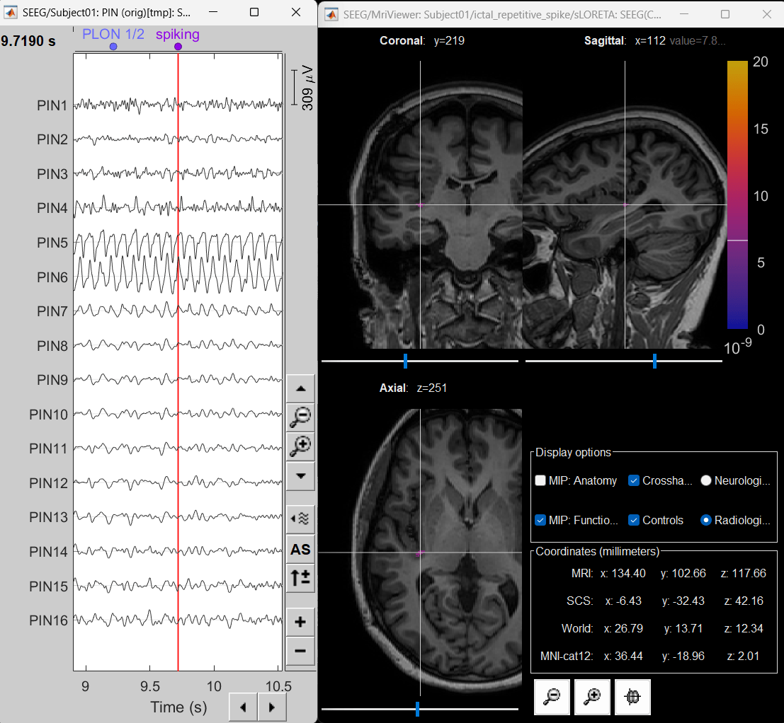
- The peak of the rhythmic activity localized on the patch of the cortex as seen in the MRI Viewer above.
Additional Documentation
Forum discussions
Articles
Yash Shashank Vakilna, Deniz Atilgan, Johnson Hampson, Chinmay Chinara, Takfarinas Medani, Richard M. Leahy, Nuria Lacuey, Samden D. Lhatoo, Sandipan Pati, John C. Mosher, Jay R. Gavvala.
Time-Frequency Fingerprint Analysis in SEEG Source-Space to Identify the Epileptogenic Zone.
Annals of Clinical and Translational Neurology 2025.
Related tutorials
Scripting
The following script from the Brainstorm distribution reproduces the analysis presented in this tutorial page: brainstorm3/toolbox/script/tutorial_seizure_fingerprinting.m
