|
Size: 5415
Comment:
|
Size: 7703
Comment:
|
| Deletions are marked like this. | Additions are marked like this. |
| Line 1: | Line 1: |
| = Bad channels and bad segments = ''Authors: Francois Tadel, Elizabeth Bock'' |
= Tutorial 11: Bad channels [Under construction] = ''Authors: Francois Tadel, Elizabeth Bock, Sylvain Baillet'' It is common during the acquisition to have a few sensors that are recording values that will not be usable in the data analysis. In MEG, a sensor can be damaged or unstable. In EEG, the quality of the connection between the electrode and the subject scalp is sometimes too low to record anything interesting. It is important to identify the sensors with poor signal quality at an early stage of the pre-processing, because the efficiency of the artifact removal will depend on it. If you try to remove blink and cardiac artifacts with some bad sensors it may not work very well, and worse, it will propagate the bad signals to all the channels. This tutorial will explain the various ways we have to handle the bad channels. Note that the recordings from this auditory experiment do not contain any bad sensors, therefore the entire tutorial is optional. If you are not interested, you can skip it and will still be able to follow the next tutorials. |
| Line 6: | Line 12: |
| = From auditory = == Bad channels == |
<<TAG(Advanced)>> == Identifying bad channels == Some bad channels are easy to detect, their signals look either completely off or totally flat compared with the other surrounding sensors. Some others are more difficult to identify. You may be able to observe that something looks wrong in various ways (the examples below are taken from other datasets): * In the PSD file we always recommend to compute for all the datasets (power spectrum density): <<BR>><<BR>> * Simply looking at the signals traces: <<BR>><<BR>> * Looking at a 2D sensor topography, if one sensor always has different values from its neighbors: <<BR>><<BR>> * In the source maps, if you see only one region of the cortex activated all the time. <<TAG(Advanced)>> == Marking bad channels == |
| Line 9: | Line 26: |
| . {{http://neuroimage.usc.edu/brainstorm/Tutorials/Auditory?action=AttachFile&do=get&target=badchannel02.gif|badchannel02.gif|height="200",width="456",class="attachment"}} * Right-click on '''Run01 '''> Good/bad channels > Mark some channels as bad . > '''MRT51, MLO52''' * Right-click on '''Run02 '''> Good/bad channels > Mark some channels as bad . > '''MRT51, ''''''MLO52, MLO42, MLO43''' |
|
| Line 10: | Line 32: |
| {{http://neuroimage.usc.edu/brainstorm/Tutorials/Auditory?action=AttachFile&do=get&target=badchannel02.gif|badchannel02.gif|height="200",width="456",class="attachment"}} * Right-click on '''Run01 '''> Good/bad channels > Mark some channels as bad > '''MRT51, MLO52''' * Right-click on '''Run02 '''> Good/bad channels > Mark some channels as bad > '''MRT51, ''''''MLO52, MLO42, MLO43''' |
<<TAG(Advanced)>> |
| Line 16: | Line 34: |
| = From CTF = | |
| Line 42: | Line 59: |
| * Note that if you click on a row in this window, it will select the corresponding channel in the time series and topography figures. | * Note that if you click on a row in this window, it will select the corresponding channel in the time series and topography figures. => TO CHECK |
| Line 53: | Line 70: |
| {{{ ADD BAD CHANNEL MONTAGE }}} = From auditory = == Bad segments == * At this point, you should review the entire files, by pages of a few seconds scrolling with the F3 key, to identify all the bad channels and the noisy segments of recordings. Do this with the the EOG channel open at the same time to identify saccades or blinks that were not completely corrected with the SSP projectors. As this is a complicated task that requires some expertise, we have prepared a list of bad segments for these datasets. * Open '''Run01'''. In the Record tab, select '''File > Add events from file''': * File name: sample_auditory/data/S01_AEF_20131218_01_notch/'''events_bad_01.mat ''' * File type: Brainstorm (events*.mat) * It adds '''12 bad segments''' to the file. |
<<TAG(Advanced)>> |
| Line 64: | Line 72: |
| * Open '''Run02'''. In the Record tab, select '''File > Add events from file''': * File name: sample_auditory/data/S01_AEF_20131218_02_notch/'''events_bad_02.mat ''' * File type: Brainstorm (events*.mat) * It adds '''9 bad segments''' and '''16 saccades''' to the file. |
== Montage: Bad channels == <<TAG(Advanced)>> == Epoching and averaging == At this stage of the analysis, the database contains only links to raw files. The list of bad channels is saved separately for each dataset. When you import epochs from a continuous file, the list of bad channels will be copied from the raw file to all the imported data files. Then you will be able to redefine this list for each epoch individually, tagging more channels as bad, or including back the ones that are ok. This way it is possible to exclude from the analysis channels that are too noisy in a few trials only, for instance because of some movement artifacts. When averaging, if an epoch contains one bad channel, this bad channel is excluded from the average but all the other channels are kept. It means that not all the channels have the same number of trials for calculating the average. This allows to keep more data in the studies with a low number of trials and lots of noise. <<TAG(Advanced)>> == On the hard drive == The list of bad channels is saved for each data file separately, in the field '''ChannelFlag'''. This vector indicates for each channel #i if it is good (ChannelFlag(i)=''' 1''') or bad (ChannelFlag(i)=''' -1'''). Right-click on a link to a continuous file > File > View file contents: {{attachment:bad_file.gif}} <<EmbedContent("http://neuroimage.usc.edu/bst/get_prevnext.php?prev=Tutorials/ArtifactsFilter&next=Tutorials/ArtifactsDetect")>> <<EmbedContent(http://neuroimage.usc.edu/bst/get_feedback.php?Tutorials/BadChannels)>> |
Tutorial 11: Bad channels [Under construction]
Authors: Francois Tadel, Elizabeth Bock, Sylvain Baillet
It is common during the acquisition to have a few sensors that are recording values that will not be usable in the data analysis. In MEG, a sensor can be damaged or unstable. In EEG, the quality of the connection between the electrode and the subject scalp is sometimes too low to record anything interesting.
It is important to identify the sensors with poor signal quality at an early stage of the pre-processing, because the efficiency of the artifact removal will depend on it. If you try to remove blink and cardiac artifacts with some bad sensors it may not work very well, and worse, it will propagate the bad signals to all the channels.
This tutorial will explain the various ways we have to handle the bad channels. Note that the recordings from this auditory experiment do not contain any bad sensors, therefore the entire tutorial is optional. If you are not interested, you can skip it and will still be able to follow the next tutorials.
Contents
Identifying bad channels
Some bad channels are easy to detect, their signals look either completely off or totally flat compared with the other surrounding sensors. Some others are more difficult to identify. You may be able to observe that something looks wrong in various ways (the examples below are taken from other datasets):
In the PSD file we always recommend to compute for all the datasets (power spectrum density):
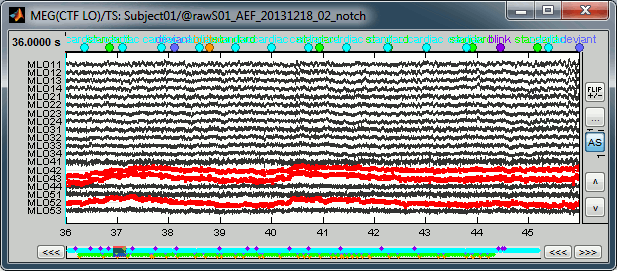
Simply looking at the signals traces:
Looking at a 2D sensor topography, if one sensor always has different values from its neighbors:
- In the source maps, if you see only one region of the cortex activated all the time.
Marking bad channels
- During the visual exploration, some channels appeared generally noisier than the others. Example:
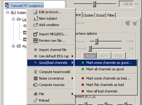
Right-click on Run01 > Good/bad channels > Mark some channels as bad
> MRT51, MLO52
Right-click on Run02 > Good/bad channels > Mark some channels as bad
> MRT51, MLO52, MLO42, MLO43
Bad channels
If you find out that a sensor has unexpected values, that are not coherent with the other surrounding sensors, you can choose to ignore it in the displays and in the source estimation process. In the channel file, each channel has a flag which indicates if it is good or bad. You may also import recordings files that already have some bad channels defined.
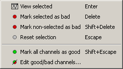
Select a few channels with one of the method described above: click on the time series, click on the sensors dots, right-click and move to select a group of sensors. Then right-click in one of the figures and check out the Channels sub-menu:

View selected: Show the time series of the selected sensors
Mark selected as bad: Remove sensors from the display and all the further computations
Mark non-selected as bad: Keep only the selected channels
Reset selection: Unselect all the selected sensors
Mark all channels as good: Brings back all the channels to display
Edit good/bad channels: Opens an interface that looks like the channel editor, but with one extra column to edit the status (good or bad) of each channel.
Mark channels as bad: Right-click > Channels > Mark selected as bad, or press Delete key. The sensors should disappear in all figures, and the topography view (2D sensors cap) is updated so that the interpolation on the 2D surface now ignores the bad channels.
Get the channels back: two options
Right-click on figure > Channels > Mark all channels as good
Right-click on figure > Channels > Edit good/bad channels... : this menu open a window very similar to the Channel Editor window introduced in previous tutorials, but without the annoying location and orientation values, and with green and red dots. Click on the dots to mark a channel as good or bad.

Note that if you click on a row in this window, it will select the corresponding channel in the time series and topography figures. => TO CHECK
- Close this window to save the changes.
Batching this from the database explorer:
- You will find a "Channels" menu for any node in the tree that contains recordings.
- If you do this on the level of a node, the operation will be applied recursively to all the recordings contained in the node. This way, you can quickly set that the channel 63 is always bad, or that electrode 43 is not working for subject #12, without having to visualize all the recordings one after the other.
The View all bad channels command displays the list of all the bad channels in all the files in the Messages tab, in main Brainstorm window.

Important notes:
The good/bad channel flags are stored in the recordings files, not in the channel files. So if you marked some channels as bad in the ERF data file, there are still considered as good in the Std data file.
Montage: Bad channels
Epoching and averaging
At this stage of the analysis, the database contains only links to raw files. The list of bad channels is saved separately for each dataset.
When you import epochs from a continuous file, the list of bad channels will be copied from the raw file to all the imported data files. Then you will be able to redefine this list for each epoch individually, tagging more channels as bad, or including back the ones that are ok. This way it is possible to exclude from the analysis channels that are too noisy in a few trials only, for instance because of some movement artifacts.
When averaging, if an epoch contains one bad channel, this bad channel is excluded from the average but all the other channels are kept. It means that not all the channels have the same number of trials for calculating the average. This allows to keep more data in the studies with a low number of trials and lots of noise.
On the hard drive
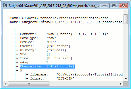
The list of bad channels is saved for each data file separately, in the field ChannelFlag. This vector indicates for each channel #i if it is good (ChannelFlag(i)= 1) or bad (ChannelFlag(i)= -1).
Right-click on a link to a continuous file > File > View file contents:


