|
Size: 2965
Comment:
|
Size: 9328
Comment:
|
| Deletions are marked like this. | Additions are marked like this. |
| Line 1: | Line 1: |
| = SSP Cookbook = ''Authors: Elizabeth Bock, Francois Tadel'' |
|
| Line 3: | Line 6: |
| = General Strategies = | <<TableOfContents(2,2)>> == General Strategies == |
| Line 12: | Line 17: |
| = Example 1: Metal in the mouth = | == Example 1: removing artifacts that are continuous == |
| Line 15: | Line 20: |
| The first step is to identify the artifact and channel(s) that are most affected. After scanning though the data, it appears there are two artifacts that are throughout the recording. | The first step is to identify the artifact and channel(s) that are most affected. After scanning though the data, it appears there are some artifacts present throughout the recording. |
| Line 17: | Line 22: |
| {{attachment:dental_and_sensor_artifacts.png||height="500",width="600"}} | {{attachment:dental_and_sensor_artifacts.png||height="442",width="531"}} |
| Line 19: | Line 24: |
| First, slower perturbations in the posterior temporal areas, as seen in the channels highlighted in red. Then there are and sharp 'jumps', highlighted in blue, which do not seem to be physiological. In addition, performing a power spectrum density (PSD) helps identify the channels and the frequencies which are most affected by these artifacts. | First, slower perturbations in the posterior temporal areas, as seen in the channels highlighted in red. Then there are sharp 'jumps', highlighted in blue, which do not seem to be physiological, but instead are most likely sensor noise. We can also see artifacts from the heart. |
| Line 21: | Line 26: |
| {{attachment:PSD_topo_artifacts.png||height="300",width="600"}} | In addition, performing a power spectrum density (PSD) helps identify the channels and the frequencies which are most affected by these artifacts. {{attachment:PSD_topo_artifacts.png||height="231",width="555"}} |
| Line 37: | Line 44: |
| 1. Review the resulting projectors and find component(s) that eliminates the artifact. Be sure to review the topography and the time series of the component to be sure you are only removing the artifact. | 1. Review the resulting projectors and find component(s) that eliminate the artifact. Be sure to review the topography and the time series of the component to confirm you are only removing the artifact. <<BR>><<BR>> {{attachment:eight_components_PCA.png||height="312",width="468"}} 1. We can see here that the first two components are most likely artifacts. Selecting these two does a very good job of removing the artifact. <<BR>><<BR>> {{attachment:dental_and_sensor_artifacts_cleaned.png||height="500",width="600"}} 1. Now do the same for cardiac events. Detect the events either from the ECG channel or from an MEG sensor. In this case, we do not have an extra ECG channel and therefore MRT41 is used. Compute the SSP on those cardiac events. Select the appropriate component. I chose the first one component because it represented the artifact. Before (left) and after (right) cardiac SSP correction. <<BR>><<BR>> {{attachment:cardiac_artifact_before.png||height="250",width="300"}} {{attachment:cardiac_artifact_after.png||height="250",width="300"}} |
| Line 39: | Line 48: |
| {{attachment:eight_components_PCA.png||height="400",width="600"}} We can see here that the first two components are most likely artifacts. Selecting these two does a very good job of removing the artifact. | |
| Line 41: | Line 49: |
| 1. Now do the same for cardiac events. Select the appropriate component. Here I chose the first one only. | == Example 2: define an SSP from the topography of an artifact == Here is an example with an artifact from a 3D video monitor that was placed inside the MSR. Reviewing the MEG channels and power spectrum reveals a strong artifact in the frontal sensors at 24Hz and its harmonics. We also see eye blink artifact. {{attachment:artifacts_before_SSPs.png||height="500",width="600"}} If we zoom in a bit to see the artifact clearer, we can see that there is a strong repeating topography. We will make a projector with this topography. {{attachment:grab_SSP_from_topo.png||height="400",width="250"}} Right-click on the topography > '''Snapshot > Use as SSP projector'''. Now just the eyeblinks remain. Detect the eye blink events (with either the EOG channel or one of the MEG channels showing the artifact). Compute the SSP and select the appropriate projector. The resulting projectors and the clean data are shown here: {{attachment:SSP_topos_for_artifacts.png||height="500",width="600"}} {{attachment:artifacts_after_SSPs.png||height="500",width="600"}} == Example 3: using the average artifact to define an SSP == After detecting heartbeats and creating an SSP projector, there was some residual artifacts remaining. Here is an optional workflow to remove that entire artifact: 1. Delete any existing cardiac SSP. 1. Using the Artifacts menu, select SSP: Generic * Time window: this should be the time window of the artifact * Event name: cardiac * Event window: [-40,40]ms * Frequency band: [4,40]Hz. Here I am opening up the freq range from the standard because my artifact seems to be better defined in this range * Sensor types: MEG * Compute using existing: check this box * Save averaged artifact: check this box * Method to calculate: choose PCA 1. Select the first component, then save. 1. In the database, you will have two new files representing the average cardiac artifact '''(before)''' and '''(after)''' 1. From the file marked '''(after)''', find the maximum peak. You may want to only look at a subset of sensors, here I have only the frontal and temporal sensors 1. Open a topography: <<BR>><<BR>> {{attachment:cardiac_leftover.png||height="323",width="403"}} 1. Right click the topography and select '''Snapshot > Save as SSP projector''' and save to disk 1. Open the '''link to raw file''' and the dialog Artifacts > Select active projectors 1. Load your saved projector into this dialog (open file icon in the upper-left corner) and apply. == Artifacts evaluation == One efficient way of representing the impact of this artifact correction is to epoch the recordings around the artifacts before and after the correction. Use the same time window as the one used in the SSP options around each marker, and average all the segments of recordings. The examples below are related with the [[http://neuroimage.usc.edu/brainstorm/Tutorials/MedianNerveCtf|CTF median nerve tutorial]]. === Eye blinks === {{http://neuroimage.usc.edu/brainstorm/Tutorials/TutRawSsp?action=AttachFile&do=get&target=blinkDb.gif|blinkDb.gif|height="263",width="283",class="attachment"}} The following image represents the file '''"blink_uncorrected / Avg: blink"''', which is the average of the 18 identified blinks '''before''' the SSP correction, [-200,+200]ms around the "blink" events. The time series, the 2D topography at the peak (t = 0ms), and the mapping on the cortex of these fields, using the basic inverse model calculated in the previous tutorial. {{http://neuroimage.usc.edu/brainstorm/Tutorials/TutRawSsp?action=AttachFile&do=get&target=blinkBefore.gif|blinkBefore.gif|height="177",width="533",class="attachment"}} The next image represents the file '''"blink_ssp / Avg: blink"''', which is the exact same thing, but '''after '''the SSP correction. The artifact is gone. If you do this and you can still see some clear evoked component in the time series figure, the SSP correction was not efficient: the artifact is not properly identified, or you should select different components using the "Select active projectors" window. {{http://neuroimage.usc.edu/brainstorm/Tutorials/TutRawSsp?action=AttachFile&do=get&target=blinkAfter.gif|blinkAfter.gif|height="177",width="533",class="attachment"}} === Heartbeats === We can do the same thing with the heartbeats: epoch [-40,+40]ms around the "cardiac" events, average the trials, and review the event-related fields at three instants: The peak of the '''P wave''' (t = '''-30ms'''): {{http://neuroimage.usc.edu/brainstorm/Tutorials/TutRawSsp?action=AttachFile&do=get&target=cardiacP.gif|cardiacP.gif|height="178",width="534",class="attachment"}} The peak of the '''QRS complex''' (t = '''0ms'''): {{http://neuroimage.usc.edu/brainstorm/Tutorials/TutRawSsp?action=AttachFile&do=get&target=cardiacQRS.gif|cardiacQRS.gif|height="178",width="534",class="attachment"}} The peak of the '''T wave''' (t = '''25ms'''): {{http://neuroimage.usc.edu/brainstorm/Tutorials/TutRawSsp?action=AttachFile&do=get&target=cardiacT.gif|cardiacT.gif|height="178",width="534",class="attachment"}} These peaks may look big, but they are in fact much smaller (300 fT for the average of 346 repetitions) than what we observed for the eye blinks (1500 fT for 18 repetitions). You can notice that none of these topographies are similar to the components we obtained after calculating the SSP for the cardiac artifact. We don't know how to correct this artifact, it doesn't look too bad in terms of recordings contamination. |
SSP Cookbook
Authors: Elizabeth Bock, Francois Tadel
Removing artifacts from MEG recordings using Signal Space Projections can sometimes be very efficient. Here are a few tricks to help you remove artifacts from your data that are ongoing or repeating.
Contents
General Strategies
We typically use one of three strategies to define an SSP projector:
1. PCA analysis over one continuous epoch (i.e. the entire recording), for which the artifact is ongoing
2. PCA analysis for concatenated 'events', for which the artifact is discrete and repeating in the recording
3. Visual identification of one topography that represents the artifact and is converted to an SSP projector.
Example 1: removing artifacts that are continuous
Here the subject has metal dental work that moves when he breathes.
The first step is to identify the artifact and channel(s) that are most affected. After scanning though the data, it appears there are some artifacts present throughout the recording.
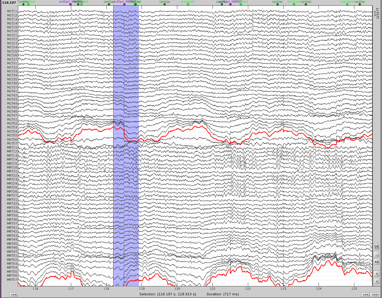
First, slower perturbations in the posterior temporal areas, as seen in the channels highlighted in red. Then there are sharp 'jumps', highlighted in blue, which do not seem to be physiological, but instead are most likely sensor noise. We can also see artifacts from the heart.
In addition, performing a power spectrum density (PSD) helps identify the channels and the frequencies which are most affected by these artifacts.
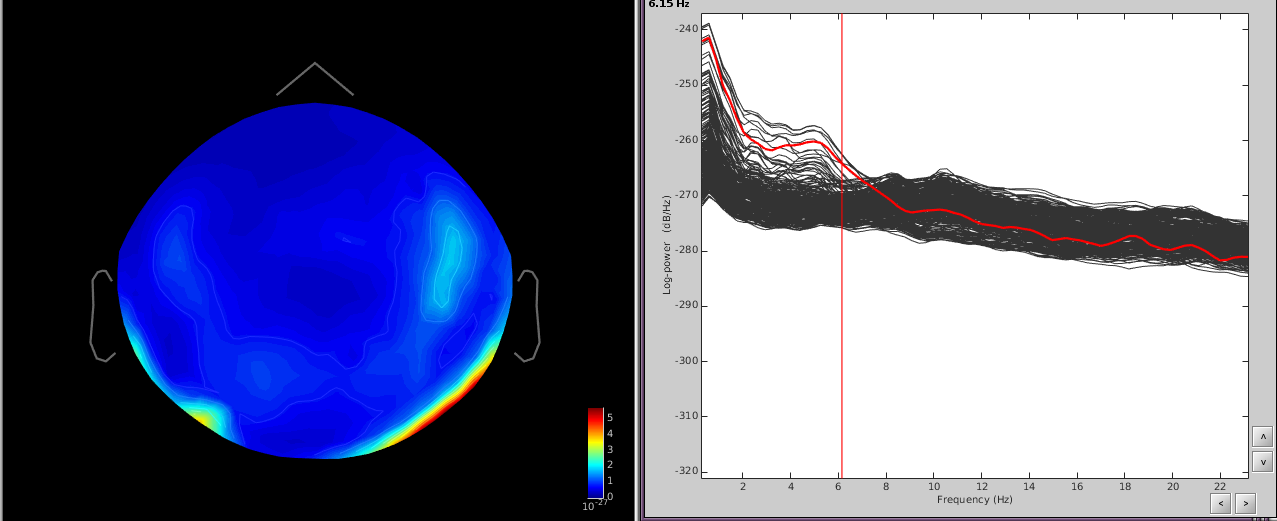
The temporal channels have higher power in the lower freq ([0,6]Hz) and the topography shows a dipole below the posterior part of the sensor array.
Since the slower artifact is ongoing and not necessarily a well-defined 'event', we will use the first strategy.
- Using the Artifacts menu, select SSP: Generic
- Time window: this should be the time window of the artifact. Here I use the first 100 seconds of the recording since the event is well defined in this time, but you can use longer times to better define the event if necessary.
- Event name: empty
- Event window: ignore this
- Frequency band: from the PSD I can see that the artifact is mostly defined in [0.5,10]Hz. If you know the freq band of the artifact, you should adjust this accordingly, if not, you can use a more broadband to get an overall view.
- Sensor types: MEG
- Compute using existing: uncheck this box
- Save averaged artifact: uncheck this box
- Method to calculate: choose PCA
- Run the process
Review the resulting projectors and find component(s) that eliminate the artifact. Be sure to review the topography and the time series of the component to confirm you are only removing the artifact.
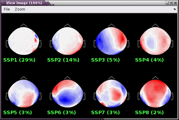
We can see here that the first two components are most likely artifacts. Selecting these two does a very good job of removing the artifact.
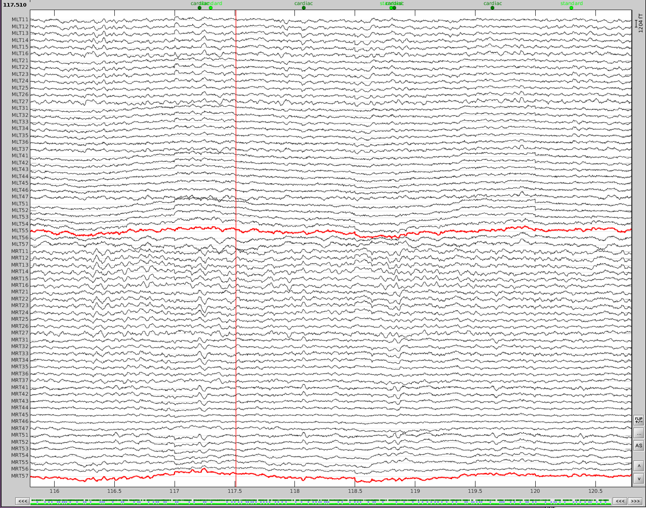
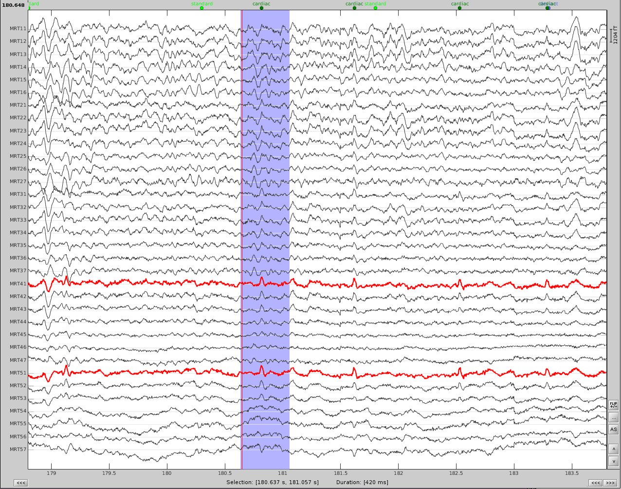
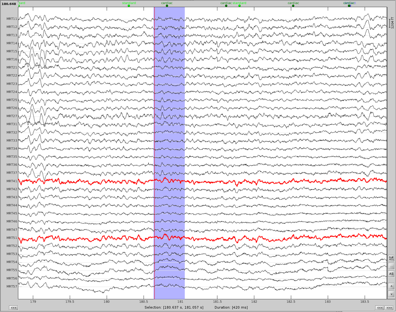
Now do the same for cardiac events. Detect the events either from the ECG channel or from an MEG sensor. In this case, we do not have an extra ECG channel and therefore MRT41 is used. Compute the SSP on those cardiac events. Select the appropriate component. I chose the first one component because it represented the artifact. Before (left) and after (right) cardiac SSP correction.
Example 2: define an SSP from the topography of an artifact
Here is an example with an artifact from a 3D video monitor that was placed inside the MSR.
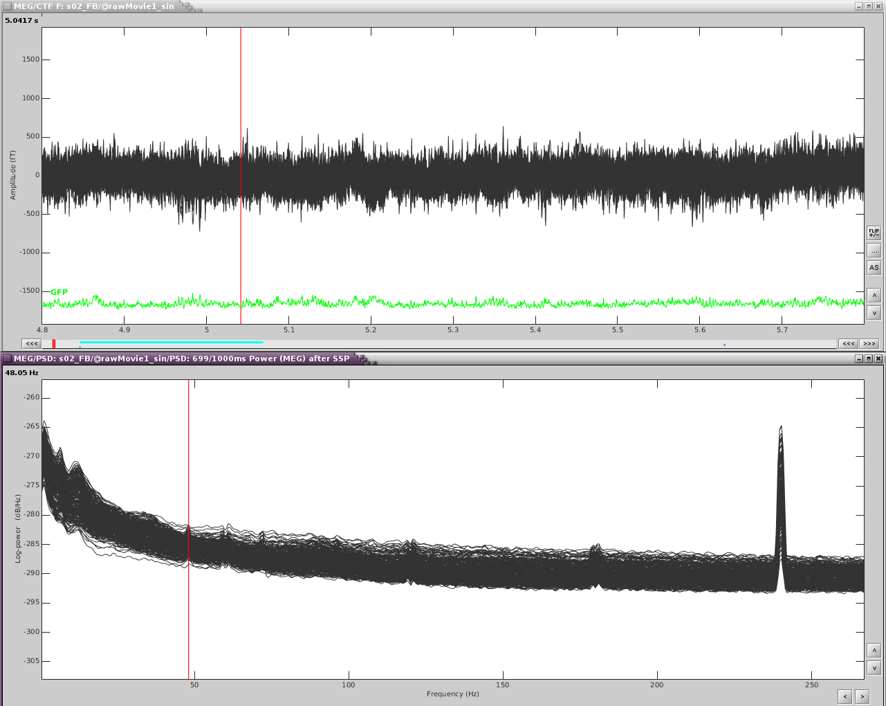
Reviewing the MEG channels and power spectrum reveals a strong artifact in the frontal sensors at 24Hz and its harmonics. We also see eye blink artifact.
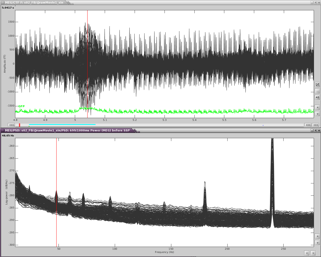
If we zoom in a bit to see the artifact clearer, we can see that there is a strong repeating topography. We will make a projector with this topography. 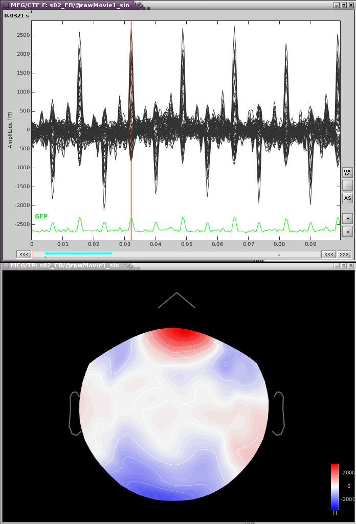
Right-click on the topography > Snapshot > Use as SSP projector.
Now just the eyeblinks remain. Detect the eye blink events (with either the EOG channel or one of the MEG channels showing the artifact). Compute the SSP and select the appropriate projector.
The resulting projectors and the clean data are shown here: 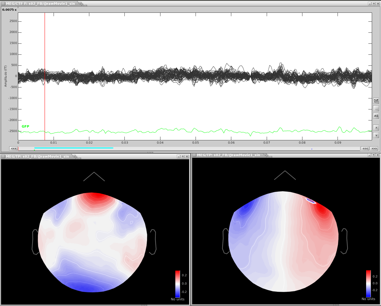
Example 3: using the average artifact to define an SSP
After detecting heartbeats and creating an SSP projector, there was some residual artifacts remaining. Here is an optional workflow to remove that entire artifact:
- Delete any existing cardiac SSP.
- Using the Artifacts menu, select SSP: Generic
- Time window: this should be the time window of the artifact
- Event name: cardiac
- Event window: [-40,40]ms
- Frequency band: [4,40]Hz. Here I am opening up the freq range from the standard because my artifact seems to be better defined in this range
- Sensor types: MEG
- Compute using existing: check this box
- Save averaged artifact: check this box
- Method to calculate: choose PCA
- Select the first component, then save.
In the database, you will have two new files representing the average cardiac artifact (before) and (after)
From the file marked (after), find the maximum peak. You may want to only look at a subset of sensors, here I have only the frontal and temporal sensors
Open a topography:
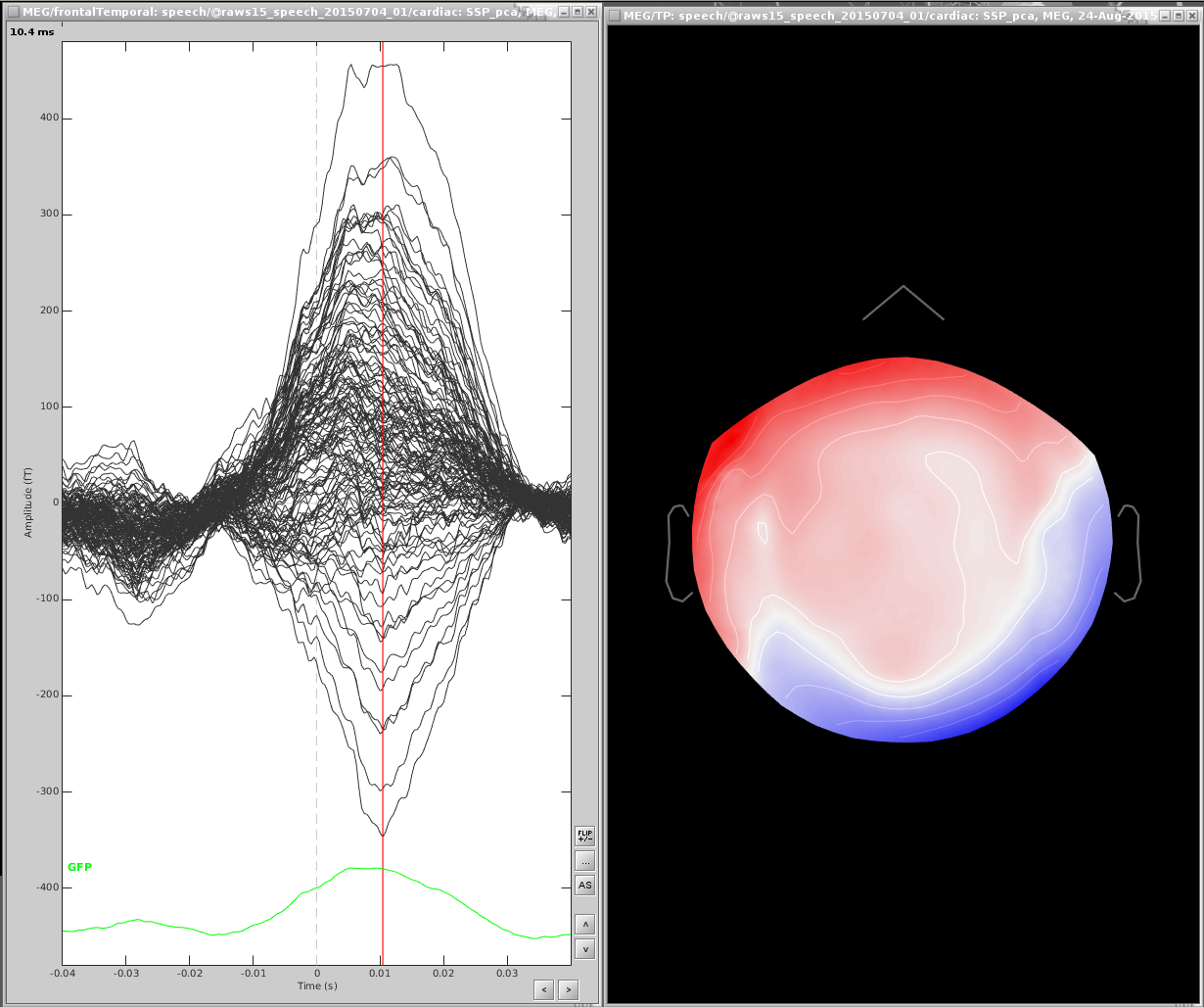
Right click the topography and select Snapshot > Save as SSP projector and save to disk
Open the link to raw file and the dialog Artifacts > Select active projectors
- Load your saved projector into this dialog (open file icon in the upper-left corner) and apply.
Artifacts evaluation
One efficient way of representing the impact of this artifact correction is to epoch the recordings around the artifacts before and after the correction. Use the same time window as the one used in the SSP options around each marker, and average all the segments of recordings. The examples below are related with the CTF median nerve tutorial.
Eye blinks
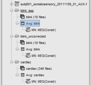
The following image represents the file "blink_uncorrected / Avg: blink", which is the average of the 18 identified blinks before the SSP correction, [-200,+200]ms around the "blink" events. The time series, the 2D topography at the peak (t = 0ms), and the mapping on the cortex of these fields, using the basic inverse model calculated in the previous tutorial.

The next image represents the file "blink_ssp / Avg: blink", which is the exact same thing, but after the SSP correction. The artifact is gone. If you do this and you can still see some clear evoked component in the time series figure, the SSP correction was not efficient: the artifact is not properly identified, or you should select different components using the "Select active projectors" window.

Heartbeats
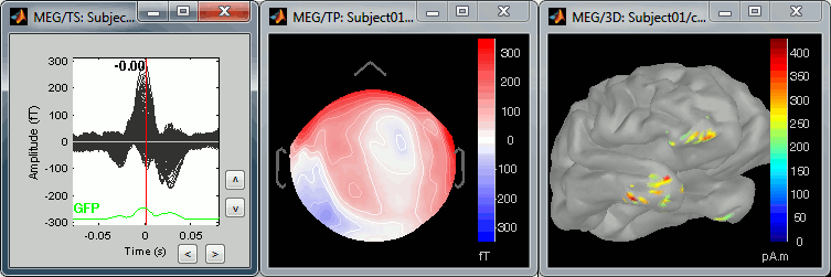
We can do the same thing with the heartbeats: epoch [-40,+40]ms around the "cardiac" events, average the trials, and review the event-related fields at three instants:
The peak of the P wave (t = -30ms):

The peak of the QRS complex (t = 0ms):
The peak of the T wave (t = 25ms):
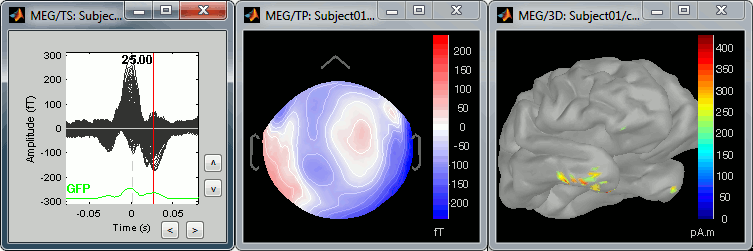
These peaks may look big, but they are in fact much smaller (300 fT for the average of 346 repetitions) than what we observed for the eye blinks (1500 fT for 18 repetitions). You can notice that none of these topographies are similar to the components we obtained after calculating the SSP for the cardiac artifact. We don't know how to correct this artifact, it doesn't look too bad in terms of recordings contamination.
