|
Size: 5484
Comment:
|
Size: 15872
Comment:
|
| Deletions are marked like this. | Additions are marked like this. |
| Line 1: | Line 1: |
| = Tutorial 8: Fixing stimulation delays = | = Tutorial 8: Stimulation delays = |
| Line 3: | Line 3: |
The event markers that are saved in the data files might have delays. In most cases, the stimulation triggers saved by the acquisition system indicate when the stimulation computer requested a stimulus to be presented. After this request, the equipment used to deliver the stimulus to the subject (projector, screen, sound card, electric or tactile device) always introduce some delays. Therefore, the stimulus triggers are saved before the instant when the subject actually receives the stimulus. For accurate timing of the brain responses, it is very important to estimate these delays precisely and if possible to account for them in the analysis. This tutorial explains how to correct for the different types of delays in the case of an auditory study, if the output of the sound card is saved together with the MEG/EEG recordings. A similar approach can be used in visual experiments using a photodiode. |
|
| Line 6: | Line 10: |
| == Existing delays == The delays present in those recordings are documented on this page: [[DatasetAuditory|MEG auditory dataset]]. |
== Note for beginners == This entire tutorial can be considered as advanced. It is very important to correct for the stimulation delays in your experiments, but if you are not using any stimulation device, you do not need this information. However, if you skip the entire tutorial, you will have uncorrected delays and it will be more difficult to follow along the rest of the tutorials. Just go quickly through the actions that are required and skip all the explanations. |
| Line 9: | Line 13: |
| * '''Delay #1''': Between the stim markers (channel UDIO001) and the moment where the sound card plays the sound (channel UADC001). This is mostly due to the software running on the computer (stimulation software, operating system, sound card drivers, sound card electronics). The delay can be measured from the recorded files by comparing the triggers in the two channels: Delay''' between 11.5ms and 12.8ms''' (std = 0.3ms) This delay is '''not constant''', we will need to correct for it. | <<TAG(Advanced)>> |
| Line 11: | Line 15: |
| * '''Delay #2''': Between when the sound card plays the sound and when the subject receives the sound in the ears. This is the time it takes for the transducer to convert the analog audio signal into a sound, plus the time it takes to the sound to travel through the air tubes from the transducer to the subject's ears. This delay cannot be estimated from the recorded signals: before the acquisition, we placed a sound meter at the extremity of the tubes to record when the sound is delivered. Delay '''between 4.8ms and 5.0ms''' (std = 0.08ms). At a sampling rate of 2400Hz, this delay can be considered '''constant''', we will not compensate for it. | == Documented delays == Reminder: The full description of this auditory dataset is available on this page: [[DatasetIntroduction|Introduction dataset]]. |
| Line 13: | Line 18: |
| * '''Delay #3''': The CTF MEG systems have a constant delay of '''4 samples''' between the MEG/EEG channels and the analog channels (such as the audio signal UADC001), because of an anti-aliasing filtered that is applied to the first and not the second. This translate here to a '''constant delay''' of '''1.7ms'''. | '''Delay #1''': Production of the sound |
| Line 15: | Line 20: |
| * '''Delay #4''': When correcting of delay #1, the process we use to detect the beginning of the triggers on the audio signal (UADC001) sets the trigger in the middle of the ramp between silence and the beep. We "over-compensate" the delay #1 by 1.7ms. This can be considered as '''constant delay '''of about '''-1.7ms'''. | * The stimulation software generates the request to play a sound, the corresponding trigger is recorded in the stim channel by the MEG acquisition software. * Then this request goes through different software layers (operating system, sound card drivers) and the sound card electronics. The sound card produces an analog sound signal that is sent at the same time to the subject and to MEG acquisition system. The acquisition software saves a copy of it in an audio channel together with the MEG recordings and the stim channel. * The delay can be measured from the recorded files by comparing the triggers in the stim channel and the actual sound in the audio channel. We measured delays''' between 11.5ms and 12.8ms''' (std = 0.3ms). These delays are '''not constant''', we should adjust for them. Jitters in the stimulus triggers cause the different trials to be aligned incorrectly in time, hence "blurred" averaged responses. |
| Line 17: | Line 24: |
| * '''Uncorrected delays''': We will correct for the delay #1, and keep the other delays (#2, #3 and #4). After we compensate for delay #1 our MEG signals will have a '''constant delay '''of about 4.9 + 1.7 - 1.7 = '''4.9 ms'''. We decide not to compensate for those delays because they do not introduce any jitter in the responses and they are not going to change anything in the interpretation of the data. | '''Delay #2''': Transmission of the sound |
| Line 19: | Line 26: |
| == Stimulation triggers delay == === Evaluation === * Right-click on Run01/Link to raw file > '''Stim '''> Display time series (stimuls channel, UDIO001) Right-click on Run01/Link to raw file > '''ADC V''' > Display time series (audio signal generated, UADC001) |
* The sound card plays the sound, the audio signal is sent with a cable to two transducers located in the MEG room, close to the subject. This causes no observable delay. |
| Line 23: | Line 28: |
| * In the Record tab, set the duration of display window to '''0.200s'''. Jump to the third event in the "standard" category. | * The transducers convert the analog audio signal into a sound (air vibration). Then this sound is delivered to the subject's ears through air tubes. These two operations cause a small delay. |
| Line 25: | Line 30: |
| * We can observe that there is a delay of about '''13ms''' between the time where the stimulus trigger is generated by the stimulation computer and the moment where the sound is actually played by the sound card of the stimulation computer ('''delay #1'''). This is matching the documentation of the experiment in the first section of this tutorial. . {{http://neuroimage.usc.edu/brainstorm/Tutorials/Auditory?action=AttachFile&do=get&target=stim1.gif|stim1.gif|height="282",width="590",class="attachment"}} |
* This delay cannot be estimated from the recorded signals: before the acquisition, we placed a sound meter at the extremity of the tubes to record when the sound is delivered. We measured delays '''between 4.8ms and 5.0ms''' (std = 0.08ms). At a sampling rate of 2400Hz, this delay can be considered '''constant''', we will not compensate for it. |
| Line 28: | Line 32: |
| === Correction === * '''Delay #1''': We can detect the triggers from the analog audio signal (ADC V/UADC001) rather than using the events already detected by the CTF software from the stim channel (Stim/UDIO001). * Drag and drop '''Run01 '''and '''Run02 '''to the Process1 box. * Add '''twice''' the process "'''Events > Detect analog triggers'''". Once with event name="standard_fix" and reference event="standard". Once with event name="deviant_fix" and reference event="deviant". Set the other options as illustrated below: . {{http://neuroimage.usc.edu/brainstorm/Tutorials/Auditory?action=AttachFile&do=get&target=stim2.gif|stim2.gif|class="attachment"}} * Open Run01 (channel ADC V) to evaluate the correction that was performed by this process. If you look at the third trigger in the "standard" category, you can measure a 14.6ms delay between the original event "standard" and the new event "standard_fix". . {{http://neuroimage.usc.edu/brainstorm/Tutorials/Auditory?action=AttachFile&do=get&target=stim3.gif|stim3.gif|height="151",width="570",class="attachment"}} * Open '''Run01''' to re-organize the event categories: * '''Delete '''the unused event categories: '''standard''', '''deviant'''. * '''Rename '''standard_fix and deviant_fix to '''standard''' and '''deviant'''. * Open '''Run02''' and do the same cleaning operations: . {{http://neuroimage.usc.edu/brainstorm/Tutorials/Auditory?action=AttachFile&do=get&target=stim5.gif|stim5.gif|height="149",width="502",class="attachment"}} * '''Important note''': We compensated for the jittered delays (delay #1), but not for the other ones (delays #2, #3 and #4). There is still a''' constant 5ms delay''' between the stimulus triggers ("standard" and "deviant") and the time where the sound actually reaches the subject's ears. |
'''Delay #3''': Recording of the signals |
| Line 42: | Line 34: |
| <<EmbedContent("http://neuroimage.usc.edu/bst/get_prevnext.php?prev=Tutorials/EventMarkers&next=Tutorials/ArtifactsFilter")>> | * The CTF MEG systems have a constant delay of '''4 samples''' between the analog channels (MEG/EEG, auditory,etc) and the digital channels (stim, buttons, etc), because of an anti-aliasing filter that is applied to the first and not the second. This translates here to a '''constant 'negative' delay''' of '''1.7ms''', meaning the analog channels are delayed when compared to the stim channels. * Many acquisition devices (EEG and MEG) have similar hidden features, read correctly the documentation of your hardware before analyzing your recordings. <<BR>> {{attachment:delays_sketch_small.gif}} <<BR>> == Evaluation of the delay == Let's display simultaneously the stimulus channel and the audio signal. * Right-click AEF#01 link > '''Stim '''> Display time series: The stim channel is '''UPPT001'''. * Right-click AEF#01 link > '''ADC V''' > Display time series: The audio channel is '''UADC001'''. * In the Record tab, set the duration of display window to '''0.200s'''. * Jump to the third event in the "standard" category. * We can observe that there is a delay of about '''13ms''' between the time where the stimulus trigger is generated by the stimulation computer and the moment where the sound is actually played by the sound card of the stimulation computer ('''delay #1'''). <<BR>><<BR>> {{attachment:delays_evaluate.gif||height="241",width="631"}} * What we want to do is to discard the existing triggers and replace them with new, more accurate ones created based on the audio signal. We need to detect the beginning of the sound on analog channel UADC001. * Note that the representation of the oscillation of the sound tone is really bad here. The frequency of this standard tone is 440Hz. It was correctly captured by the original recordings at 2400Hz, but not in the downsampled version we use in the introduction tutorials. It should still be good enough for performing the detection of the stimulus. == Detection of the analog triggers == ==== Detecting the standard triggers ==== Run the detection of the "standard" audio triggers on channel UADC001 for file AEF#01. * Keep the same windows open as previously. * In the Record tab, select the menu '''File > Detect analog triggers'''. * This opens the '''Pipeline editor''' window with the process '''Events > Detect analog triggers''' selected. This window will be introduced later, for now we will just use it to configure the process options. Configure it as illustrated below:<<BR>><<BR>> {{attachment:delays_detect.gif||height="497",width="558"}} <<TAG(Advanced)>> <<BR>> '''Explanation of the options''' (for future reference, you can skip this now): * '''Event name''': Name of the new event category created to store the detected triggers. <<BR>>We can start with the event "standard", and call the corrected triggers "standard_fix". * '''Channel name''': Channel on which to perform the detection (audio channel UADC001). * '''Time window''': Time segment on which you want to detect analog triggers. <<BR>>Leave the default time window or check the box "All file", it will do the same thing. * '''Amplitude threshold''': A trigger is set whenever the amplitude of the signal increases above X times the standard deviation of the signal over the entire file. Increase this value if you want the detection to be less sensitive. * '''Min duration between two events''': If the event we want to detect is an oscillation, we don't want to detect a trigger at each cycle of this oscillation. After we detect one, we stop the detection for a short time. Use a value that is always between the duration of the stimulus (here 100ms) and the inter-stimulus interval (here > 700ms). * '''Apply band-pass filter before the detection''': Use this option if the effect you are trying to detect is more visible in a specific frequency band. In our case, the effect is obvious in the broadband signal, we don't need to apply any filter. * '''Reference''': If you have an approximation of the triggers timing, you can specify it here. Here we have the events "standard" and we want to detect a trigger in their neighborhood. <<BR>>If we do not use this option, the process creates only one new group with all the audio signals, without distinction between the deviant and standard tones. * '''Detect falling edge''' (instead of rising edge): Detects the end of the tone instead of the beginning. * '''Remove DC offset''': If the signal on which we perform the detection does not oscillate around zero or has a high continuous component, removing the average of the signal can improve the detection. This should be selected when using a photodiode with a pull-up resistor. * '''Enable classification''': Tries to automatically classify the different types of events that are detected based on the morphology of the signal in the neighborhood of the trigger. ==== Results of the detection ==== * Navigate through a few of the new "standard_fix" events to evaluate if the result is correct. You can observe that the corrected triggers are consistently detected after the rising portion of the audio signal, two samples after the last sample where the signal was flat. * This means that we are over-compensating delay #1 by 3.3ms. But at least this delay is constant and will not affect the analysis. We can count this as a '''constant delay''' of '''-3.3ms'''.<<BR>><<BR>> {{attachment:delays_results.gif||height="237",width="520"}} ==== Detecting the deviant triggers ==== * Repeat the same operation for the deviant tones. * In the Record tab, select the menu '''File > Detect analog triggers'''. <<BR>><<BR>> {{attachment:delays_deviant.gif||height="522",width="589"}} ==== Some cleaning ==== * We will use the corrected triggers only, we can delete the original ones to avoiding any confusion. * Delete the event groups "deviant" and "standard" (select them and press the '''Delete '''key). * Rename the group "deviant_fix" into "deviant" (double-click on the group name). * Rename the group "standard_fix" into "standard". * Close all: Answer YES to save the modifications.<<BR>><<BR>> {{attachment:delays_final.gif}} == Repeat on acquisition run #02 == Repeat all the exact same operations on the link to file''' AEF#02''': * Right-click AEF#01 link > '''Stim '''> Display time series: The stim channel is '''UPPT001'''. * Right-click AEF#01 link > '''ADC V''' > Display time series: The audio channel is '''UADC001'''. * In the Record tab, select menu '''File > Detect analog triggers''': '''standard_fix''' * In the Record tab, select menu '''File > Detect analog triggers''': '''deviant_fix''' * Check that the events are correctly detected. * Delete the event groups "deviant" and "standard" (select them and press the '''Delete '''key). * Rename the group "deviant_fix" into "deviant" (double-click on the group name). * Rename the group "standard_fix" into "standard". * Close all: Answer YES to save the modifications. == Delays after this correction == We compensated for the jittered delays (delay #1), but not for hardware delays (delay #2). Note that delay #3 is no longer an issue since we are not using the orginal stim markers, but the more accurate audio signal. The final delay between the "standard_fix" triggers and the moment when the subject gets the stimulus is now delay #2 and the over-compensation. '''Final constant delay''': 4.9 - 3.3 = '''1.6ms''' We decide not to compensate for this delay because it is very short and does not introduce any jitter in the responses. It is not going to change anything in the interpretation of the data. <<TAG(Advanced)>> == Detection of the button responses == As mentioned in the previous tutorial, the '''button''' markers are also incorrect. The subject presses a button with the right index finger when a deviant is presented. Because of some issues with the way this CTF system saves the triggers, some are doubled (49 markers for 40 button presses). We don't really need to correct this category of events because we will not use them in the introduction tutorials. You can skip this section if you are not interested in parsing digital channels. The digital channel Stim/'''UDIO001''' contains the inputs from the response button box (optic device, negligible delay). Each bit of the integer value on this channel corresponds to the activation of one button. We can read this channel directy to get accurate timing for the button presses. * Right-click AEF#01 link > '''Stim '''> Display time series: The response channel is '''UDIO001'''. * In the Record tab: Set the page duration to '''3 seconds'''. * Browse through a few '''button '''markers, notice that some of them are doubled. <<BR>>Explanation: The CTF acquisition software may generate a trigger at the beginning of an epoch (remember that this file has been recorded as contiguous epochs of 1 second) when a stim line is in a non-zero state at the first sample of the epoch. When the button is still pressed when a new block of 1s starts, we get an erroneous trigger. <<BR>><<BR>> {{attachment:delays_button.gif||height="193",width="540"}} * Note on the DC removal: You may see the base value of the UDIO001 channel "below" the zero line. This is an effect of the DC correction that is applied on the fly to the recordings. The average of the signals over the current page is subtracted from them. To restore the real value you can uncheck the '''[DC]''' button in the Record tab. Atlernatively, just remember that the reference line for a channel doesn't necessarily mean "zero" when the DC removal option is on. * In the Record tab, select menu '''File > Read events from channel''': '''UDIO001 / Value''' <<BR>><<BR>> {{attachment:delays_button_detect.gif||height="312",width="583"}} * You get a new event category '''64''', this is the value of the UDIO001 at the detected transitions. There are only 40 of them, one for the each button press. We can use this as a replacement for the original '''button '''category.<<BR>><<BR>> {{attachment:delays_button_fix.gif||height="208",width="535"}} * To make things clearer: delete the '''button''' group and rename '''64''' into '''button'''. <<BR>><<BR>> {{attachment:delays_button_final.gif||height="86",width="228"}} * Close all: Answer YES to save the modifications. * Optionally, you can repeat the same operation for the other run, AEF#02. But we will not use the "button" markers in the analysis, so it is not very useful. * Note that these events will have delay #3 (when compared to MEG/EEG) since they are recorded on a digital channel. <<TAG(Advanced)>> == Another example: visual experiments == We have discussed here how we could compensate for the delays introduced in an auditory experiment using a copy of the audio signal saved in the recordings. A similar approach can be used for other types of experiments. Another typical example is the use a photodiode in visual experiments. When sending images to the subject using a screen or a projector, we usually have jittered delays coming from the stimulation computer (software and hardware) and due to the refresh rate of the device. These delays are difficult to account for in the analysis. To detect accurately when the stimulus is presented to the subject, we can place a photodiode in the MEG room. The diode produce a change in voltage when presented with a change in light input, for example black to white on the screen. This is typically managed with a small square of light in the corner of the stimulus screen - turning white when the stimulus appears on the screen and then black at all other times. The signal coming from this photodiode can be recorded together with the MEG/EEG signals, just like we did here for the audio signal. Depending on the photodiode, it is recommended to use a pull-up resistor when recording the signal. Then we can detect the triggers on the photodiode output channel using the menu "detect analog triggers", including the use of the 'Remove DC offset' option. <<HTML(<!-- END-PAGE -->)>> <<EmbedContent("http://neuroimage.usc.edu/bst/get_prevnext.php?prev=Tutorials/EventMarkers&next=Tutorials/PipelineEditor")>> |
Tutorial 8: Stimulation delays
Authors: Francois Tadel, Elizabeth Bock
The event markers that are saved in the data files might have delays. In most cases, the stimulation triggers saved by the acquisition system indicate when the stimulation computer requested a stimulus to be presented. After this request, the equipment used to deliver the stimulus to the subject (projector, screen, sound card, electric or tactile device) always introduce some delays. Therefore, the stimulus triggers are saved before the instant when the subject actually receives the stimulus.
For accurate timing of the brain responses, it is very important to estimate these delays precisely and if possible to account for them in the analysis. This tutorial explains how to correct for the different types of delays in the case of an auditory study, if the output of the sound card is saved together with the MEG/EEG recordings. A similar approach can be used in visual experiments using a photodiode.
Contents
Note for beginners
This entire tutorial can be considered as advanced. It is very important to correct for the stimulation delays in your experiments, but if you are not using any stimulation device, you do not need this information. However, if you skip the entire tutorial, you will have uncorrected delays and it will be more difficult to follow along the rest of the tutorials. Just go quickly through the actions that are required and skip all the explanations.
Documented delays
Reminder: The full description of this auditory dataset is available on this page: Introduction dataset.
Delay #1: Production of the sound
- The stimulation software generates the request to play a sound, the corresponding trigger is recorded in the stim channel by the MEG acquisition software.
- Then this request goes through different software layers (operating system, sound card drivers) and the sound card electronics. The sound card produces an analog sound signal that is sent at the same time to the subject and to MEG acquisition system. The acquisition software saves a copy of it in an audio channel together with the MEG recordings and the stim channel.
The delay can be measured from the recorded files by comparing the triggers in the stim channel and the actual sound in the audio channel. We measured delays between 11.5ms and 12.8ms (std = 0.3ms). These delays are not constant, we should adjust for them. Jitters in the stimulus triggers cause the different trials to be aligned incorrectly in time, hence "blurred" averaged responses.
Delay #2: Transmission of the sound
- The sound card plays the sound, the audio signal is sent with a cable to two transducers located in the MEG room, close to the subject. This causes no observable delay.
- The transducers convert the analog audio signal into a sound (air vibration). Then this sound is delivered to the subject's ears through air tubes. These two operations cause a small delay.
This delay cannot be estimated from the recorded signals: before the acquisition, we placed a sound meter at the extremity of the tubes to record when the sound is delivered. We measured delays between 4.8ms and 5.0ms (std = 0.08ms). At a sampling rate of 2400Hz, this delay can be considered constant, we will not compensate for it.
Delay #3: Recording of the signals
The CTF MEG systems have a constant delay of 4 samples between the analog channels (MEG/EEG, auditory,etc) and the digital channels (stim, buttons, etc), because of an anti-aliasing filter that is applied to the first and not the second. This translates here to a constant 'negative' delay of 1.7ms, meaning the analog channels are delayed when compared to the stim channels.
- Many acquisition devices (EEG and MEG) have similar hidden features, read correctly the documentation of your hardware before analyzing your recordings.

Evaluation of the delay
Let's display simultaneously the stimulus channel and the audio signal.
Right-click AEF#01 link > Stim > Display time series: The stim channel is UPPT001.
Right-click AEF#01 link > ADC V > Display time series: The audio channel is UADC001.
In the Record tab, set the duration of display window to 0.200s.
- Jump to the third event in the "standard" category.
We can observe that there is a delay of about 13ms between the time where the stimulus trigger is generated by the stimulation computer and the moment where the sound is actually played by the sound card of the stimulation computer (delay #1).
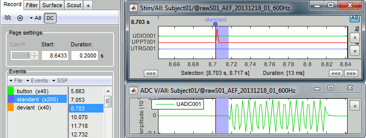
- What we want to do is to discard the existing triggers and replace them with new, more accurate ones created based on the audio signal. We need to detect the beginning of the sound on analog channel UADC001.
- Note that the representation of the oscillation of the sound tone is really bad here. The frequency of this standard tone is 440Hz. It was correctly captured by the original recordings at 2400Hz, but not in the downsampled version we use in the introduction tutorials. It should still be good enough for performing the detection of the stimulus.
Detection of the analog triggers
Detecting the standard triggers
Run the detection of the "standard" audio triggers on channel UADC001 for file AEF#01.
- Keep the same windows open as previously.
In the Record tab, select the menu File > Detect analog triggers.
This opens the Pipeline editor window with the process Events > Detect analog triggers selected. This window will be introduced later, for now we will just use it to configure the process options. Configure it as illustrated below:
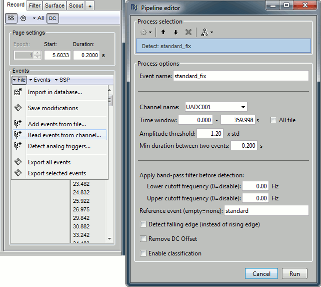
Explanation of the options (for future reference, you can skip this now):
Event name: Name of the new event category created to store the detected triggers.
We can start with the event "standard", and call the corrected triggers "standard_fix".Channel name: Channel on which to perform the detection (audio channel UADC001).
Time window: Time segment on which you want to detect analog triggers.
Leave the default time window or check the box "All file", it will do the same thing.Amplitude threshold: A trigger is set whenever the amplitude of the signal increases above X times the standard deviation of the signal over the entire file. Increase this value if you want the detection to be less sensitive.
Min duration between two events: If the event we want to detect is an oscillation, we don't want to detect a trigger at each cycle of this oscillation. After we detect one, we stop the detection for a short time. Use a value that is always between the duration of the stimulus (here 100ms) and the inter-stimulus interval (here > 700ms).
Apply band-pass filter before the detection: Use this option if the effect you are trying to detect is more visible in a specific frequency band. In our case, the effect is obvious in the broadband signal, we don't need to apply any filter.
Reference: If you have an approximation of the triggers timing, you can specify it here. Here we have the events "standard" and we want to detect a trigger in their neighborhood.
If we do not use this option, the process creates only one new group with all the audio signals, without distinction between the deviant and standard tones.Detect falling edge (instead of rising edge): Detects the end of the tone instead of the beginning.
Remove DC offset: If the signal on which we perform the detection does not oscillate around zero or has a high continuous component, removing the average of the signal can improve the detection. This should be selected when using a photodiode with a pull-up resistor.
Enable classification: Tries to automatically classify the different types of events that are detected based on the morphology of the signal in the neighborhood of the trigger.
Results of the detection
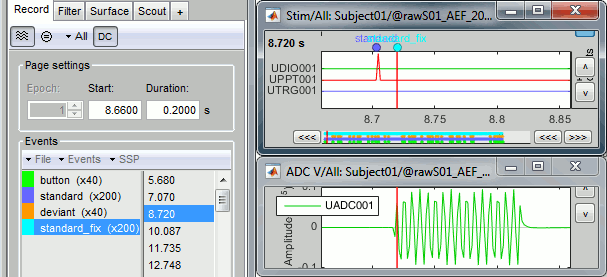
- Navigate through a few of the new "standard_fix" events to evaluate if the result is correct. You can observe that the corrected triggers are consistently detected after the rising portion of the audio signal, two samples after the last sample where the signal was flat.
This means that we are over-compensating delay #1 by 3.3ms. But at least this delay is constant and will not affect the analysis. We can count this as a constant delay of -3.3ms.
Detecting the deviant triggers
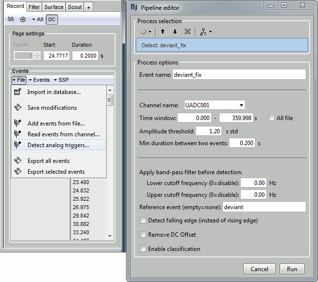
- Repeat the same operation for the deviant tones.
In the Record tab, select the menu File > Detect analog triggers.
Some cleaning
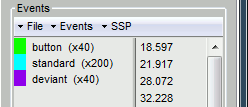
- We will use the corrected triggers only, we can delete the original ones to avoiding any confusion.
Delete the event groups "deviant" and "standard" (select them and press the Delete key).
- Rename the group "deviant_fix" into "deviant" (double-click on the group name).
- Rename the group "standard_fix" into "standard".
Close all: Answer YES to save the modifications.
Repeat on acquisition run #02
Repeat all the exact same operations on the link to file AEF#02:
Right-click AEF#01 link > Stim > Display time series: The stim channel is UPPT001.
Right-click AEF#01 link > ADC V > Display time series: The audio channel is UADC001.
In the Record tab, select menu File > Detect analog triggers: standard_fix
In the Record tab, select menu File > Detect analog triggers: deviant_fix
- Check that the events are correctly detected.
Delete the event groups "deviant" and "standard" (select them and press the Delete key).
- Rename the group "deviant_fix" into "deviant" (double-click on the group name).
- Rename the group "standard_fix" into "standard".
- Close all: Answer YES to save the modifications.
Delays after this correction
We compensated for the jittered delays (delay #1), but not for hardware delays (delay #2). Note that delay #3 is no longer an issue since we are not using the orginal stim markers, but the more accurate audio signal. The final delay between the "standard_fix" triggers and the moment when the subject gets the stimulus is now delay #2 and the over-compensation.
Final constant delay: 4.9 - 3.3 = 1.6ms
We decide not to compensate for this delay because it is very short and does not introduce any jitter in the responses. It is not going to change anything in the interpretation of the data.
Detection of the button responses
As mentioned in the previous tutorial, the button markers are also incorrect. The subject presses a button with the right index finger when a deviant is presented. Because of some issues with the way this CTF system saves the triggers, some are doubled (49 markers for 40 button presses). We don't really need to correct this category of events because we will not use them in the introduction tutorials. You can skip this section if you are not interested in parsing digital channels.
The digital channel Stim/UDIO001 contains the inputs from the response button box (optic device, negligible delay). Each bit of the integer value on this channel corresponds to the activation of one button. We can read this channel directy to get accurate timing for the button presses.
Right-click AEF#01 link > Stim > Display time series: The response channel is UDIO001.
In the Record tab: Set the page duration to 3 seconds.
Browse through a few button markers, notice that some of them are doubled.
Explanation: The CTF acquisition software may generate a trigger at the beginning of an epoch (remember that this file has been recorded as contiguous epochs of 1 second) when a stim line is in a non-zero state at the first sample of the epoch. When the button is still pressed when a new block of 1s starts, we get an erroneous trigger.
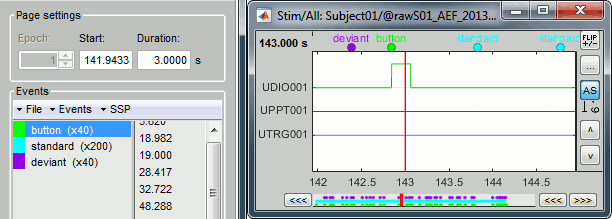
Note on the DC removal: You may see the base value of the UDIO001 channel "below" the zero line. This is an effect of the DC correction that is applied on the fly to the recordings. The average of the signals over the current page is subtracted from them. To restore the real value you can uncheck the [DC] button in the Record tab. Atlernatively, just remember that the reference line for a channel doesn't necessarily mean "zero" when the DC removal option is on.
In the Record tab, select menu File > Read events from channel: UDIO001 / Value
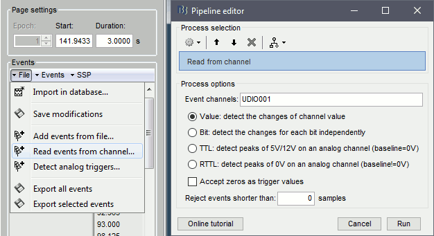
You get a new event category 64, this is the value of the UDIO001 at the detected transitions. There are only 40 of them, one for the each button press. We can use this as a replacement for the original button category.
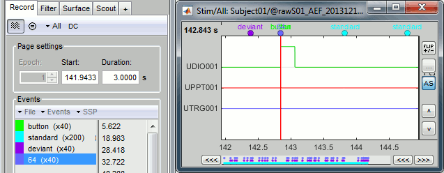
To make things clearer: delete the button group and rename 64 into button.

- Close all: Answer YES to save the modifications.
- Optionally, you can repeat the same operation for the other run, AEF#02. But we will not use the "button" markers in the analysis, so it is not very useful.
- Note that these events will have delay #3 (when compared to MEG/EEG) since they are recorded on a digital channel.
Another example: visual experiments
We have discussed here how we could compensate for the delays introduced in an auditory experiment using a copy of the audio signal saved in the recordings. A similar approach can be used for other types of experiments. Another typical example is the use a photodiode in visual experiments.
When sending images to the subject using a screen or a projector, we usually have jittered delays coming from the stimulation computer (software and hardware) and due to the refresh rate of the device. These delays are difficult to account for in the analysis.
To detect accurately when the stimulus is presented to the subject, we can place a photodiode in the MEG room. The diode produce a change in voltage when presented with a change in light input, for example black to white on the screen. This is typically managed with a small square of light in the corner of the stimulus screen - turning white when the stimulus appears on the screen and then black at all other times. The signal coming from this photodiode can be recorded together with the MEG/EEG signals, just like we did here for the audio signal. Depending on the photodiode, it is recommended to use a pull-up resistor when recording the signal. Then we can detect the triggers on the photodiode output channel using the menu "detect analog triggers", including the use of the 'Remove DC offset' option.
