|
Size: 6268
Comment:
|
Size: 6265
Comment:
|
| Deletions are marked like this. | Additions are marked like this. |
| Line 9: | Line 9: |
| <<Include(DatasetAuditory, , from="\<\<HTML\(\<!-- START-HEADPOINTS --\>\)\>\>", to="\<\<HTML\(\<!-- STOP-HEADPOINTS --\>\)\>\>")>> | <<Include(DatasetAuditory, , from="\<\<HTML\(\<!-- START-HEADPOINTS --\>\)\>\>", to="\<\<HTML\(\<!-- STOP-HEADPOINTS --\>\)\>\>")>> |
Tutorial 8: Fixing stimulation delays
Authors: Francois Tadel, Elizabeth Bock
Existing delays
The full description of this dataset is available on this page: Introduction dataset.
Head shape and fiducial points
3D digitization using a Polhemus Fastrak device driven by Brainstorm (S01_20131218_*.pos)
More information: Digitize EEG electrodes and head shape
- The output file is copied to each .ds folder and contains the following entries:
- The position of the center of CTF coils
The position of the anatomical references we use in Brainstorm:
Nasion and connections tragus/helix, as illustrated here.
- Around 150 head points distributed on the hard parts of the head (no soft tissues)
Evaluation of the delay
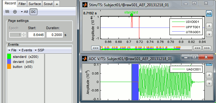
Right-click on Run01/Link to raw file > Stim > Display time series (stimuls channel, UDIO001) Right-click on Run01/Link to raw file > ADC V > Display time series (audio signal generated, UADC001)
In the Record tab, set the duration of display window to 0.200s. Jump to the third event in the "standard" category.
We can observe that there is a delay of about 13ms between the time where the stimulus trigger is generated by the stimulation computer and the moment where the sound is actually played by the sound card of the stimulation computer (delay #1). This is matching the documentation of the experiment in the first section of this tutorial.
Selecting files to process
First thing to do is to define the files you are going to process. This is done easily by picking files or folders in the database explorer and dropping them in the empty list of the Process1 tab.
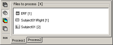
- Drag and drop the following nodes in the Process1 list: Right/ERF (recordings), Right (condition), and Subject01 (subject)
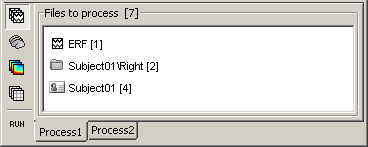
- The number in the brackets next to each node represents the number of data files that where found in each of them. The node ERF "contains" only itself (1), Subject01/Right contains ERF and Std files (2), and Subject01 contains 2 conditions x 2 recordings (4).
- The total number of files, ie. the sum of all those values, appears in the title of the panel "Files to process [7]".
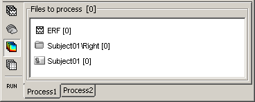
- The buttons on the left side allow you to select what type of file you want to process: Recordings, sources, time-frequency, other. Now select the second button "Sources". All the counts are updated and now reflect the number of sources files that are found for each node.
- If you select the third button "Time-frequency", you would see "0" everywhere because there are no time-frequency decompositions in the database yet.
Now clear the list from all the files. You may either right-click on the list (popup menu Clear list), or select all the nodes (holding Shift or Crtl key) and then press the Delete key.
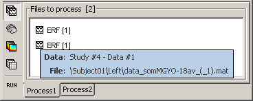
Select both files Left/ERF and Right/ERF in the tree (holding Ctrl key), and put the in Process list. We are going to apply some functions on those two files. You cannot distinguish them after they are dropped in the list, because they are both referred as "ERP". If at some point you need to know what is in the list, just leave you mouse over a node for a few seconds, and a tooltip would give you information about it. Just like in the database explorer.
Correction
Delay #1: We can detect the triggers from the analog audio signal (ADC V/UADC001) rather than using the events already detected by the CTF software from the stim channel (Stim/UDIO001).
Drag and drop Run01 and Run02 to the Process1 box.
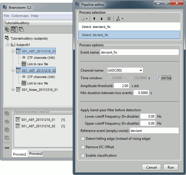
Add twice the process "Events > Detect analog triggers". Once with event name="standard_fix" and reference event="standard". Once with event name="deviant_fix" and reference event="deviant". Set the other options as illustrated below:
- Open Run01 (channel ADC V) to evaluate the correction that was performed by this process. If you look at the third trigger in the "standard" category, you can measure a 14.6ms delay between the original event "standard" and the new event "standard_fix".
Open Run01 to re-organize the event categories:
Delete the unused event categories: standard, deviant.
Rename standard_fix and deviant_fix to standard and deviant.
Open Run02 and do the same cleaning operations:
Important note: We compensated for the jittered delays (delay #1), but not for the other ones (delays #2, #3 and #4). There is still a constant 5ms delay between the stimulus triggers ("standard" and "deviant") and the time where the sound actually reaches the subject's ears.
Sort analog events into event categories
Typically the analog channel contains events (like a photodiode signal) that do not contain information about which event is occurring. This can be rectified by matching the event marker from the acquisition with the events detected on the analog channel:
Run > Events > Combine stim/response
ignore ; B_AB ; A ; B
substitute ‘B’ with the photodiode event name
substitute ‘A’ with the event name of interest

