|
Size: 4125
Comment:
|
Size: 20007
Comment:
|
| Deletions are marked like this. | Additions are marked like this. |
| Line 1: | Line 1: |
| ## page was renamed from ChannelFile = Tutorial 3: = |
= Tutorial 4: Channel file / MEG-MRI coregistration = |
| Line 4: | Line 3: |
The anatomy of your subject is ready. Before we can start looking at the MEG/EEG recordings, we need to make sure that the sensors (electrodes, magnetometers or gradiometers) are properly aligned with the MRI and the surfaces of the subject. In this tutorial, we will start with a detailed description of the experiment and the files that were recorded, then we will link the original CTF files to the database in order to get access to the sensors positions, and finally we will explore the various options for aligning these sensors on the head of the subject. |
|
| Line 7: | Line 10: |
| == Access the raw file == The basic tutorials you read before explain how to import recordings in the database: this operation creates a copy of all the data in Matlab .mat files in the Brainstorm database folders. You could process continuous recordings in the same way, but the .mat format has this limitation that the entire file has to be read even when you want to access just a portion of it. Long recordings usually cannot fit in memory and have to be split in small blocks of a few seconds, which makes it very difficult to review and process. |
<<Include(DatasetIntroduction, , from="\<\<HTML\(\<!-- START-PAGE --\>\)\>\>", to="\<\<HTML\(\<!-- STOP-MEG --\>\)\>\>")>> |
| Line 10: | Line 12: |
| Brainstorm offers the possibility to visualize continuous MEG/EEG recordings in any of the supported file formats without having to fully "import" them. A link to the native file is created in the database, which can be then manipulated almost like the "imported" recording blocks. Only the description of the file is saved in the database, and when displaying it the values are read directly from the native file. | <<Include(DatasetIntroduction, , from="\<\<HTML\(\<!-- START-HEADPOINTS --\>\)\>\>", to="\<\<HTML\(\<!-- STOP-HEADPOINTS --\>\)\>\>")>> |
| Line 12: | Line 14: |
| In addition, an interface allows to edit the time markers that are saved in the file. Those markers can then be used to import the recordings in the database (ie. to do the segmentation of the continuous recordings in epochs/trials). Then the imported epochs/trials (hard copies in .mat format) can be pre-processed and averaged. | == Link the raw files to the database == * Switch to the "functional data" view. <<BR>><<BR>> {{attachment:view_functional.gif}} * Right-click on the subject folder > '''Review raw file''' * Select the file format: "'''MEG/EEG: CTF (*.ds...)'''" * Select __'''all'''__ the .ds folders in: '''sample_introduction/data''' * In the CTF file format, each session of recordings is saved in a folder with the extension "ds". The different types of information collected during each session are saved as different files in this folder (event markers, sensor definitions, bad segments, MEG recordings). |
| Line 14: | Line 21: |
| * Select the exploration mode: "Functional data (sorted by subject)"<<BR>><<BR>> {{attachment:view_functional.gif}} * Right-click on the subject node, and select: "Review raw file". Select the "MEG: CTF" file type, and pick the ds folder in "/sample_raw/Data". . {{http://neuroimage.usc.edu/brainstorm/Tutorials/TutRawViewer?action=AttachFile&do=get&target=menuReview.gif|menuReview.gif|class="attachment"}} * Then you're asked if you want to "Refine the registration with the head points". This operation improves the initial MRI/MEG registration by fitting the head points digitized before the MEG acquisition on the scalp surface with an ICP algorithm. Answer yes. Even if the result is not perfect, it usually improves the positioning of the head in the MEG helmet. The grey surface represents the head extracted from the MRI, the yellow surface represents the inside of the MEG helmet, and the green dots are the head shape points digitized with the Polhemus device; the goal is to align the green points on the grey surface. . {{http://neuroimage.usc.edu/brainstorm/Tutorials/TutRawViewer?action=AttachFile&do=get&target=refine.gif|refine.gif|class="attachment"}} {{http://neuroimage.usc.edu/brainstorm/Tutorials/TutRawViewer?action=AttachFile&do=get&target=refineBefore.gif|refineBefore.gif|class="attachment"}} {{http://neuroimage.usc.edu/brainstorm/Tutorials/TutRawViewer?action=AttachFile&do=get&target=refineAfter.gif|refineAfter.gif|class="attachment"}} * Two new files appeared in the database explorer: . {{http://neuroimage.usc.edu/brainstorm/Tutorials/TutRawViewer?action=AttachFile&do=get&target=linkInTree.gif|linkInTree.gif|class="attachment"}} * The channel file contains the definition of the sensors, exactly as when importing the files in the database with the "Import MEG/EEG" menu. It is saved in the folder ''(Common files)'', because the subject was created using the option "Yes, use one channel file per subject". Therefore, the same channel file will be used for all the folders of Subject01. * The node named "Link to raw file" contains all the information that was read from the continuous file (file format, time vector, sampling frequency, events, bad channels, path to the original file, etc.), but no recordings. The MEG and EEG values recorded will be read directly from the native file. |
* {{attachment:review_menu.gif||width="615",height="185"}} * Refine registration now? '''YES''' <<BR>>This operation is detailed in the next section.<<BR>><<BR>> {{attachment:review_refine.gif}} * Percentage of head points to ignore: '''0'''<<BR>>If you have some points that were not digitized correctly and that appear far from the head surface, you should increase this value in order to exclude them from the fit.<<BR>> {{attachment:review_outliers.gif}} |
| Line 24: | Line 25: |
| == Automatic registration == The registration between the MRI and the MEG (or EEG) is done in two steps. We start with a first approximation based on three reference points, then we refine it with the full head shape of the subject. |
|
| Line 25: | Line 28: |
| ==== Step 1: Fiducials ==== * The initial registration is based on the three fiducial points that define the [[https://neuroimage.usc.edu/brainstorm/CoordinateSystems|Subject Coordinate System]] ('''SCS'''): '''nasion''', '''left ear''', '''right ear'''. You have marked these three points in the MRI viewer in the previous tutorial. * These same three points have also been marked before the acquisition of the MEG recordings. The person who recorded this subject [[https://neuroimage.usc.edu/brainstorm/Tutorials/TutDigitize|digitized their positions]] with a tracking device (such as a Polhemus FastTrak or Patriot). The position of these points are saved in the dataset. * When we bring the MEG recordings into the Brainstorm database, we align them on the MRI using these fiducial points: we match the NAS/LPA/RPA points digitized with the ones we located in the MRI Viewer. * This registration method gives approximate results. It can be good enough in some cases, but not always because of the [[https://neuroimage.usc.edu/brainstorm/Tutorials/TutDigitize#Accuracy|imprecision of the measures]]. The tracking system is not always very precise, the points are not always easy to identify on the MRI slides, and the very definition of these points does not offer a millimeter precision. All this combined, it is easy to end with an registration error of 1cm or more. * The quality of the source analysis we will perform later is highly dependent on the quality of the registration between the sensors and the anatomy. If we start with a 1cm error, this error will be propagated everywhere in the analysis.<<BR>><<BR>> {{attachment:polhemus_setup.gif||width="291",height="180"}} {{attachment:polhemus_beth.jpg||width="140",height="188"}} |
|
| Line 26: | Line 35: |
| <<EmbedContent("http://neuroimage.usc.edu/bst/get_prevnext.php?prev=Tutorials/ExploreAnatomy&next=Tutorials/EventMarkers")>> | ==== Step 2: Head shape ==== * To improve this registration, we recommend our users to always digitize additional points on the head of the subjects: around '''100 points''' uniformly distributed on the hard parts of the head (skull from nasion to inion, eyebrows, ear contour, nose crest). Avoid marking points on the softer parts (cheeks or neck) because they may have a different shape when the subject is seated on the Polhemus chair or lying down in the MRI. More information on [[Tutorials/TutDigitize|digitizing head points]]. * We have two versions of the full head shape of the subject: one coming from the MRI (the head surface, represented in grey in the figures below) and one coming from the Polhemus digitizer at the time of the MEG/EEG acquisition (represented as green dots). * The algorithm that is executed when you chose the option "'''Refine registration with head points'''" is an iterative algorithm that tries to find a better fit between the two head shapes (grey surface and green dots), to improve the intial NAS/LPA/RPA registration. This technique usually improves significantly the registration between the MRI and the MEG/EEG sensors. * Tolerance: If you enter a percentage of head points to ignore superior to zero, the fit is performed once with all the points, then the head points the most distant to the cortex are removed, and the fit is executed a second time with the head points that are left. * The two pictures below represent the registration before and after this automatic head shape registration (left=step 1, right=step 2). The yellow surface represents the MEG helmet: the solid plastic surface in which the subject places his/her head. If you ever see the grey head surface intersecting this yellow helmet surface, there is obviously something wrong with the registration. * At the end of the import process, you can close the figure that shows the final registration.<<BR>><<BR>> {{attachment:refine_before.gif||width="300"}} {{attachment:refine_after.gif||width="300"}} * A window reporting the distance between the scalp and the head points is displayed. You can use these values as references for estimating whether you can trust the automatic registration or not. Defining whether the distances are correct or abnormal depend on your digitization setup. <<BR>><<BR>> {{attachment:refine_outliers.gif}} |
| Line 28: | Line 44: |
| <<EmbedContent(http://neuroimage.usc.edu/bst/get_feedback.php?Tutorials/ReviewRaw)>> | ==== Defaced volumes ==== When processing your own datasets, if your MRI images are [[https://neuroimage.usc.edu/brainstorm/News#March_2019|defaced]], you might need to proceed in a slightly different way. The de-identification procedures remove the nose and other facial features from the MRI. If your digitized head shape includes points on the missing parts of the head, this may cause an important bias in automatic registration. In this case it is advised to '''remove the head points below the nasion''' before proceeding to the automatic registration, as illustrated in [[https://neuroimage.usc.edu/brainstorm/Tutorials/VisualSingle#MRI_registration|this tutorial]]. == New files and folders == Many new files are now visible in the database explorer: * Three folders representing the three MEG datasets that we linked to the database. Note the tag "raw" in the icon of the folders, this means that the files are considered as new continuous files. * '''S01_AEF_20131218_01_600Hz''': Subject01, Auditory Evoked Field, 18-Dec-2013, run #01 * '''S01_AEF_20131218_02_600Hz''': Subject01, Auditory Evoked Field, 18-Dec-2013, run #02 * '''S01_Noise_20131218_02_600Hz''': Subject01, Noise recordings (no subject in the MEG) * All three have been downsampled from 2400Hz to 600Hz. Each of these new folders show two elements: * '''Channel file''': Defines the types and names of channels that were recorded, the position of the sensors, the head shape and other various details. This information has been read from the MEG datasets and saved as a new file in the database. The total number of data channels recorded in the file is indicated between parenthesis (340). * '''Link to raw file''': Link to the original file that you imported. All the relevant meta-data was read from the MEG dataset and copied inside the link itself (sampling rate, number of samples, event markers and other details about the acquisition session). But no MEG/EEG recordings were read or copied to the database. If we open this file, the values are read directly from the original files in the .ds folder. <<BR>><<BR>> {{attachment:review_tree.gif}} == Review vs Import == When trying to bring external data into the Brainstorm environment, a common source of confusion is the difference between the two popup menus Review and Import: * '''Review raw file''': Allows you to create a link to your original continuous data file. It reads the header and sensor information from the file but does not copy the recordings in the database. Most of the artifact cleaning should be done directly using these links. * '''Import MEG/EEG''': Extract segments of recordings (epochs) from an external file and saves copies of them in the Brainstorm database. You should not be using this menu until you have fully pre-processed your recordings, or if you are importing files that are already epoched or averaged. == Display the sensors == Right-click on the ''CTF channels'' file and try all the display menus: * '''CTF Helmet''': Shows a surface that represents the inner surface of the MEG helmet. * '''CTF coils (MEG)''': Display the MEG head coils of this CTF system: they are all axial gradiometers, only the coils close to the head are represented. The small squares do not represent the real shape of the sensors (the CTF coils are circular loops) but an approximation made in the forward model computation. * '''CTF coils (ALL)''': Display all the MEG sensors, including the reference magnetometers and gradiometers. The orientation of the coils is represented with a red segment. * '''MEG''': MEG sensors are represented as small white dots and can be selected by clicking on them. * '''ECG / EOG''': Ignore these menus, we do not have proper positions for these electrodes. * '''Misc''': Shows the approximate positions of the EEG electrodes (Cz and Pz). * Use the ['''Close all'''] button to close all the figures when you are done.<<BR>><<BR>> {{attachment:channel_menu.gif||width="459",height="227"}} <<BR>><<BR>> {{attachment:channel_display.gif||width="702",height="192"}} <<TAG(Advanced)>> == Sensor map == Here is a map with the full list of sensor names for this CTF system, it could be useful for navigating in the recordings. Click on the image for a larger version. [[http://neuroimage.usc.edu/brainstorm/Tutorials/ChannelFile?action=AttachFile&do=get&target=channel_map.gif|{{attachment:channel_map_small.gif|?action=AttachFile&do=view&target=snap_3conditions.jpg}}]] <<TAG(Advanced)>> == Manual registration == If the registration you get with the automatic alignment is incorrect, or if there was an issue when you digitized the position of the fiducials or the head shape, you may have to realign manually the sensors on the head. Right-click on the channel file > '''MRI Registration''': * '''Check''': Show all the possible information that may help to verify the registration. * '''Edit''': Opens a window where you can move manually the MEG helmet relative to the head. <<BR>>Read the tooltips of the buttons in the toolbar to see what is available, select an operation and then right-click+move up/down to apply it. From a scientific point of view this is not exactly a rigorous operation, but sometimes it is much better than using wrong default positions. <<BR>>'''IMPORTANT''': this refinement can only be used to better align the headshape with the digitized points - it cannot be used to correct for a subject who is poorly positioned in the helmet (i.e. you cannot move the helmet closer to the subjects head if they were not seated that way to begin with!) <<BR>><<BR>> {{attachment:channel_manual.gif||width="231",height="181"}} * '''Refine using head points''': Runs the automatic registration described earlier. * In the 3D views, the head points can be color-coded to represent the distance to the scalp. Right-click on the figure > Channels > '''Color head points by distance''' (shortcut CTRL+H). The colorbar indicates in millimeters the distance of each point to the scalp, as compute by bst_surfdist.m.<<BR>><<BR>> {{attachment:refine_dist.png}} There is nothing to change here, but remember to '''always '''check the registration scalp/sensors. <<TAG(Advanced)>> == Multiple runs and head positions == Between two acquisition runs the subject may move in the MEG helmet, the relative position of the MEG sensors with the head surface changes. At the beginning of each MEG run, the positions of the head localization coils are detected and used to update the position of the MEG sensors. * The two AEF runs 01 and 02 were acquired successively. The position of the subject's head in the MEG helmet was estimated twice, once at the beginning of each run. * To evaluate visually the displacement between the two runs, select at the same time all the channel files you want to compare (the ones for run 01 and 02), right-click > Display sensors > MEG.<<BR>><<BR>> {{attachment:channel_multiple.gif||width="500",height="281"}} * Typically, we would like to group the trials coming from multiple acquisition runs. However, because of the subject's movements between runs, it is usually not possible to directly compare the MEG values between runs. The sensors may not capture the activity coming from the same regions of the brain. * You have three options if you consider grouping information from multiple runs: * '''Method 1''': Process all the runs separately and average between runs at the source level: The more accurate option, but requires more work, computation time and storage. * '''Method 2''': Ignore movements between runs: This can be acceptable if the displacements are really minimal, less accurate but much faster to process and easier to manipulate. * '''Method 3''': Co-register properly the runs using the process Standardize > Co-register MEG runs: Can be a good option for displacements under 2cm.<<BR>>Warning: This method has not be been fully evaluated on our side, use at your own risk. Also, it does not work correctly if you have different SSP projectors calculated for multiple runs. * In this tutorial, we will illustrate only method 1: runs are not co-registered. <<TAG(Advanced)>> == Edit the channel file == Display a table with all the information about the individual channels. You can edit all the values. * Right-click on the channel of the first folder (AEF#01) > '''Edit channel file''': <<BR>><<BR>> {{attachment:channel_edit.gif||width="596",height="147"}} * '''Index''': Index of the channel in the data matrix. Can be edited to reorder the channels. * '''Name''': Name that was given to the channel by the acquisition device. * '''Type''': Type of information recordeded (MEG, EEG, EOG, ECG, EMG, Stim, Other, "Delete", etc) * You may have to change the Type for some channels. For instance if an EOG channel was saved as a regular EEG channel, you have to change its type to prevent it from being used in the source estimation. * To delete a channel from this file: select "(Delete)" in the type column. * '''Group''': Used to define sub-group of channels of the same type. * SEEG/ECOG: Each group of contacts can represent a depth electrode or a grid, and it can be plotted separately. A separate average reference montage is calculated for each group. * MEG/EEG: Not used. * '''Comment''': Additional description of the channel. * MEG sensors: Do not edit this information if it is not empty. * '''Loc''': Position of the sensor (x,y,z) in SCS coordinates. Do not modify this from the interface. <<BR>>One column per coil and per integration point (information useful for the forward modeling). * '''Orient''': Orientation of the MEG coils (x,y,z) in SCS coordinates). One column per Loc column. * '''Weight''': When there is more than one coil or integration point, the Weight field indicates the multiplication factor to apply to each of these points. * To edit the type or the comment for multiple sensors at once, select them all then right-click. * Close this figure, do not save the modifications if you made any. <<TAG(Advanced)>> == On the hard drive == Some other fields are present in the channel file that cannot be accessed with the ''Channel editor'' window. You can explore these other fields with the ''File ''menu, selecting ''View file contents'' or ''Export to Matlab'', as presented in the previous tutorial. . {{attachment:channel_contents.gif||width="566",height="317"}} ==== Structure of the channel files: channel_*.mat ==== * '''Comment ''': String that is displayed in the Brainstorm database explorer. * '''MegRefCoef''': Noise compensation matrix for CTF and 4D MEG recordings, based on some other sensors that are located far away from the head. * '''Projector''': SSP/ICA projectors used for artifact cleaning purposes. See the [[https://neuroimage.usc.edu/brainstorm/Tutorials/ArtifactsSsp#On_the_hard_drive|SSP tutorial]]. * '''TransfMeg / TransfMegLabel''': Transformations that were applied to the positions of the MEG sensors to bring them in the Brainstorm coordinate system. * '''TransfEeg'''''' / TransfEegLabel''': Same for the position of the EEG electrodes. * '''HeadPoints''': Extra head points that were digitized with a tracking system. * '''Channel''': An array that defines each channel individually (see previous section). * '''History''': Describes all the operations that were performed with Brainstorm on this file. To get a better view of this piece of information, use the menu File > View file history. * '''IntraElectrodes''': Definition of iEEG devices, documented in the [[https://neuroimage.usc.edu/brainstorm/Tutorials/Epileptogenicity#On_the_hard_drive|SEEG tutorial]]. ==== Useful functions ==== * /toolbox/io/'''import_channel.m''': Read a channel file and save it in the database. * /toolbox/io/'''in_channel_*.m''': Low-level functions for reading all the file formats. * /toolbox/io/'''in_bst_channel.m''': Read a channel file saved in the database. * /toolbox/sensors/'''channel_*.m''': Routines for manipulating channel files. * /toolbox/gui/'''view_channels'''(ChannelFile, Modality, ...): Display the sensors in a 3D figure. <<TAG(Advanced)>> == Additional documentation == * Tutorial: [[http://neuroimage.usc.edu/brainstorm/CoordinateSystems#Brainstorm_.pos_files|Coordinate systems / Brainstorm .pos files]] * Forum: [[http://neuroimage.usc.edu/forums/showthread.php?2100-co-registration-evaluation-and-Polhemus-vs-Vit-E|Polhemus headshape vs. vitamin E markers]] * Forum: [[http://neuroimage.usc.edu/forums/showthread.php?2528|Match known EEG locations to the MRI image]] * Forum: [[https://neuroimage.usc.edu/forums/t/flipping-biosemi-eeg-layout/36219/17|Flipping EEG sensors left-right]] * Forum: [[https://neuroimage.usc.edu/forums/t/flip-left-right-meg-sensor-signals/38622/2|Flipping MEG sensors left-right]] * Forum: Import the position of SEEG/ECOG contacts: [[http://neuroimage.usc.edu/forums/showthread.php?2206|Post #2206]], [[http://neuroimage.usc.edu/forums/showthread.php?1958|Post #1958]], [[http://neuroimage.usc.edu/forums/showthread.php?2357|Post #2357]] <<HTML(<!-- END-PAGE -->)>> <<EmbedContent("http://neuroimage.usc.edu/bst/get_prevnext.php?prev=Tutorials/ExploreAnatomy&next=Tutorials/ReviewRaw")>> <<EmbedContent(http://neuroimage.usc.edu/bst/get_feedback.php?Tutorials/ChannelFile)>> |
Tutorial 4: Channel file / MEG-MRI coregistration
Authors: Francois Tadel, Elizabeth Bock, Sylvain Baillet
The anatomy of your subject is ready. Before we can start looking at the MEG/EEG recordings, we need to make sure that the sensors (electrodes, magnetometers or gradiometers) are properly aligned with the MRI and the surfaces of the subject.
In this tutorial, we will start with a detailed description of the experiment and the files that were recorded, then we will link the original CTF files to the database in order to get access to the sensors positions, and finally we will explore the various options for aligning these sensors on the head of the subject.
Contents
License
This dataset (MEG and MRI data) was collected by the MEG Unit Lab, McConnell Brain Imaging Center, Montreal Neurological Institute, McGill University, Canada. The original purpose was to serve as a tutorial data example for the Brainstorm software project. It is presently released in the Public Domain, and is not subject to copyright in any jurisdiction.
We would appreciate though that you reference this dataset in your publications: please acknowledge its authors (Elizabeth Bock, Peter Donhauser, Francois Tadel and Sylvain Baillet) and cite the Brainstorm project seminal publication.
Presentation of the experiment
Experiment
- One subject, two acquisition runs of 6 minutes each.
- Subject stimulated binaurally with intra-aural earphones (air tubes+transducers), eyes opened and looking at a fixation cross on a screen.
- Each run contains:
- 200 regular beeps (440Hz).
- 40 easy deviant beeps (554.4Hz, 4 semitones higher).
- Random inter-stimulus interval: between 0.7s and 1.7s seconds, uniformly distributed.
- The subject presses a button when detecting a deviant with the right index finger.
- Auditory stimuli generated with the Matlab Psychophysics toolbox.
The specifications of this dataset were discussed initially on the FieldTrip bug tracker:
http://bugzilla.fieldtriptoolbox.org/show_bug.cgi?id=2300.
MEG acquisition
Acquisition at 2400Hz, with a CTF 275 system, subject in sitting position
- Recorded at the Montreal Neurological Institute in December 2013
- Anti-aliasing low-pass filter at 600Hz, files saved with the 3rd order gradient
Downsampled at a lower sampling rate: from 2400Hz to 600Hz: The only purpose for this resampling is to make the introduction tutorials easier to follow the on a regular computer.
- Recorded channels (340):
- 1 Stim channel indicating the presentation times of the audio stimuli: UPPT001 (#1)
- 1 Audio signal sent to the subject: UADC001 (#316)
- 1 Response channel recordings the finger taps in response to the deviants: UDIO001 (#2)
- 26 MEG reference sensors (#5-#30)
- 274 MEG axial gradiometers (#31-#304)
- 2 EEG electrodes: Cz, Pz (#305 and #306)
- 1 ECG bipolar (#307)
- 2 EOG bipolar (vertical #308, horizontal #309)
- 12 Head tracking channels: Nasion XYZ, Left XYZ, Right XYZ, Error N/L/R (#317-#328)
- 20 Unused channels (#3, #4, #310-#315, #329-340)
- 3 datasets:
S01_AEF_20131218_01_600Hz.ds: Run #1, 360s, 200 standard + 40 deviants
S01_AEF_20131218_02_600Hz.ds: Run #2, 360s, 200 standard + 40 deviants
S01_Noise_20131218_02_600Hz.ds: Empty room recordings, 30s long
- Average reaction times for the button press after a deviant tone:
Run #1: 515ms +/- 108ms
Run #2: 596ms +/- 134ms
Head shape and fiducial points
3D digitization using a Polhemus Fastrak device driven by Brainstorm (S01_20131218_01.pos)
More information: Digitize EEG electrodes and head shape
- The output file is copied to each .ds folder and contains the following entries:
- The position of the center of CTF coils.
The position of the anatomical references we use in Brainstorm:
Nasion and connections tragus/helix, as illustrated here.- Around 150 head points distributed on the hard parts of the head (no soft tissues).
Link the raw files to the database
Switch to the "functional data" view.
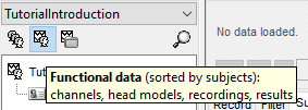
Right-click on the subject folder > Review raw file
Select the file format: "MEG/EEG: CTF (*.ds...)"
Select all the .ds folders in: sample_introduction/data
- In the CTF file format, each session of recordings is saved in a folder with the extension "ds". The different types of information collected during each session are saved as different files in this folder (event markers, sensor definitions, bad segments, MEG recordings).

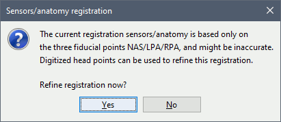
Refine registration now? YES
This operation is detailed in the next section.
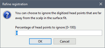
Percentage of head points to ignore: 0
If you have some points that were not digitized correctly and that appear far from the head surface, you should increase this value in order to exclude them from the fit.
Automatic registration
The registration between the MRI and the MEG (or EEG) is done in two steps. We start with a first approximation based on three reference points, then we refine it with the full head shape of the subject.
Step 1: Fiducials
The initial registration is based on the three fiducial points that define the Subject Coordinate System (SCS): nasion, left ear, right ear. You have marked these three points in the MRI viewer in the previous tutorial.
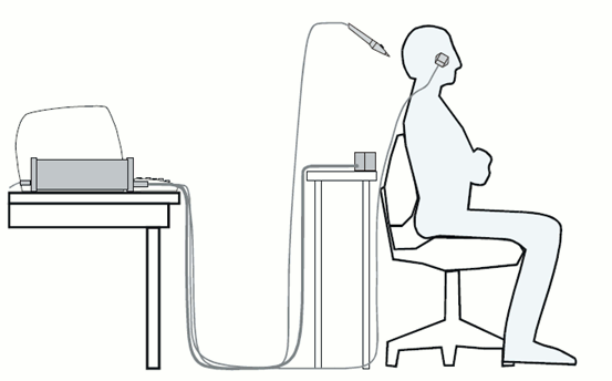
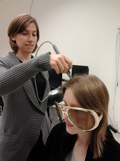
These same three points have also been marked before the acquisition of the MEG recordings. The person who recorded this subject digitized their positions with a tracking device (such as a Polhemus FastTrak or Patriot). The position of these points are saved in the dataset.
- When we bring the MEG recordings into the Brainstorm database, we align them on the MRI using these fiducial points: we match the NAS/LPA/RPA points digitized with the ones we located in the MRI Viewer.
This registration method gives approximate results. It can be good enough in some cases, but not always because of the imprecision of the measures. The tracking system is not always very precise, the points are not always easy to identify on the MRI slides, and the very definition of these points does not offer a millimeter precision. All this combined, it is easy to end with an registration error of 1cm or more.
The quality of the source analysis we will perform later is highly dependent on the quality of the registration between the sensors and the anatomy. If we start with a 1cm error, this error will be propagated everywhere in the analysis.
Step 2: Head shape
To improve this registration, we recommend our users to always digitize additional points on the head of the subjects: around 100 points uniformly distributed on the hard parts of the head (skull from nasion to inion, eyebrows, ear contour, nose crest). Avoid marking points on the softer parts (cheeks or neck) because they may have a different shape when the subject is seated on the Polhemus chair or lying down in the MRI. More information on digitizing head points.
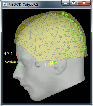
- We have two versions of the full head shape of the subject: one coming from the MRI (the head surface, represented in grey in the figures below) and one coming from the Polhemus digitizer at the time of the MEG/EEG acquisition (represented as green dots).
The algorithm that is executed when you chose the option "Refine registration with head points" is an iterative algorithm that tries to find a better fit between the two head shapes (grey surface and green dots), to improve the intial NAS/LPA/RPA registration. This technique usually improves significantly the registration between the MRI and the MEG/EEG sensors.
- Tolerance: If you enter a percentage of head points to ignore superior to zero, the fit is performed once with all the points, then the head points the most distant to the cortex are removed, and the fit is executed a second time with the head points that are left.
- The two pictures below represent the registration before and after this automatic head shape registration (left=step 1, right=step 2). The yellow surface represents the MEG helmet: the solid plastic surface in which the subject places his/her head. If you ever see the grey head surface intersecting this yellow helmet surface, there is obviously something wrong with the registration.
At the end of the import process, you can close the figure that shows the final registration.
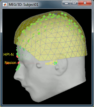
A window reporting the distance between the scalp and the head points is displayed. You can use these values as references for estimating whether you can trust the automatic registration or not. Defining whether the distances are correct or abnormal depend on your digitization setup.

Defaced volumes
When processing your own datasets, if your MRI images are defaced, you might need to proceed in a slightly different way. The de-identification procedures remove the nose and other facial features from the MRI. If your digitized head shape includes points on the missing parts of the head, this may cause an important bias in automatic registration. In this case it is advised to remove the head points below the nasion before proceeding to the automatic registration, as illustrated in this tutorial.
New files and folders
Many new files are now visible in the database explorer:
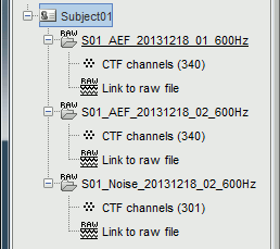
- Three folders representing the three MEG datasets that we linked to the database. Note the tag "raw" in the icon of the folders, this means that the files are considered as new continuous files.
S01_AEF_20131218_01_600Hz: Subject01, Auditory Evoked Field, 18-Dec-2013, run #01
S01_AEF_20131218_02_600Hz: Subject01, Auditory Evoked Field, 18-Dec-2013, run #02
S01_Noise_20131218_02_600Hz: Subject01, Noise recordings (no subject in the MEG)
- All three have been downsampled from 2400Hz to 600Hz.
Each of these new folders show two elements:
Channel file: Defines the types and names of channels that were recorded, the position of the sensors, the head shape and other various details. This information has been read from the MEG datasets and saved as a new file in the database. The total number of data channels recorded in the file is indicated between parenthesis (340).
Link to raw file: Link to the original file that you imported. All the relevant meta-data was read from the MEG dataset and copied inside the link itself (sampling rate, number of samples, event markers and other details about the acquisition session). But no MEG/EEG recordings were read or copied to the database. If we open this file, the values are read directly from the original files in the .ds folder.
Review vs Import
When trying to bring external data into the Brainstorm environment, a common source of confusion is the difference between the two popup menus Review and Import:
Review raw file: Allows you to create a link to your original continuous data file. It reads the header and sensor information from the file but does not copy the recordings in the database. Most of the artifact cleaning should be done directly using these links.
Import MEG/EEG: Extract segments of recordings (epochs) from an external file and saves copies of them in the Brainstorm database. You should not be using this menu until you have fully pre-processed your recordings, or if you are importing files that are already epoched or averaged.
Display the sensors
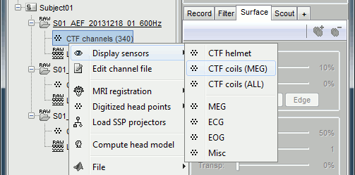
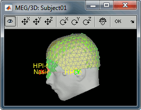
Right-click on the CTF channels file and try all the display menus:
CTF Helmet: Shows a surface that represents the inner surface of the MEG helmet.
CTF coils (MEG): Display the MEG head coils of this CTF system: they are all axial gradiometers, only the coils close to the head are represented. The small squares do not represent the real shape of the sensors (the CTF coils are circular loops) but an approximation made in the forward model computation.
CTF coils (ALL): Display all the MEG sensors, including the reference magnetometers and gradiometers. The orientation of the coils is represented with a red segment.
MEG: MEG sensors are represented as small white dots and can be selected by clicking on them.
ECG / EOG: Ignore these menus, we do not have proper positions for these electrodes.
Misc: Shows the approximate positions of the EEG electrodes (Cz and Pz).
Use the [Close all] button to close all the figures when you are done.

Sensor map
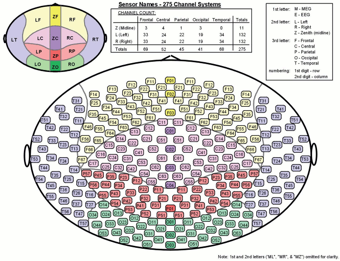
Here is a map with the full list of sensor names for this CTF system, it could be useful for navigating in the recordings. Click on the image for a larger version.
Manual registration
If the registration you get with the automatic alignment is incorrect, or if there was an issue when you digitized the position of the fiducials or the head shape, you may have to realign manually the sensors on the head. Right-click on the channel file > MRI Registration:
Check: Show all the possible information that may help to verify the registration.
Edit: Opens a window where you can move manually the MEG helmet relative to the head.
Read the tooltips of the buttons in the toolbar to see what is available, select an operation and then right-click+move up/down to apply it. From a scientific point of view this is not exactly a rigorous operation, but sometimes it is much better than using wrong default positions.
IMPORTANT: this refinement can only be used to better align the headshape with the digitized points - it cannot be used to correct for a subject who is poorly positioned in the helmet (i.e. you cannot move the helmet closer to the subjects head if they were not seated that way to begin with!)
Refine using head points: Runs the automatic registration described earlier.
In the 3D views, the head points can be color-coded to represent the distance to the scalp. Right-click on the figure > Channels > Color head points by distance (shortcut CTRL+H). The colorbar indicates in millimeters the distance of each point to the scalp, as compute by bst_surfdist.m.
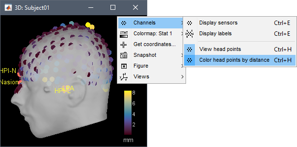
There is nothing to change here, but remember to always check the registration scalp/sensors.
Multiple runs and head positions
Between two acquisition runs the subject may move in the MEG helmet, the relative position of the MEG sensors with the head surface changes. At the beginning of each MEG run, the positions of the head localization coils are detected and used to update the position of the MEG sensors.
- The two AEF runs 01 and 02 were acquired successively. The position of the subject's head in the MEG helmet was estimated twice, once at the beginning of each run.
To evaluate visually the displacement between the two runs, select at the same time all the channel files you want to compare (the ones for run 01 and 02), right-click > Display sensors > MEG.
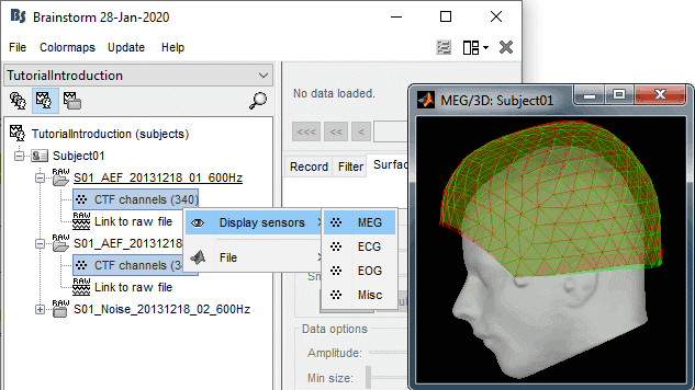
- Typically, we would like to group the trials coming from multiple acquisition runs. However, because of the subject's movements between runs, it is usually not possible to directly compare the MEG values between runs. The sensors may not capture the activity coming from the same regions of the brain.
- You have three options if you consider grouping information from multiple runs:
Method 1: Process all the runs separately and average between runs at the source level: The more accurate option, but requires more work, computation time and storage.
Method 2: Ignore movements between runs: This can be acceptable if the displacements are really minimal, less accurate but much faster to process and easier to manipulate.
Method 3: Co-register properly the runs using the process Standardize > Co-register MEG runs: Can be a good option for displacements under 2cm.
Warning: This method has not be been fully evaluated on our side, use at your own risk. Also, it does not work correctly if you have different SSP projectors calculated for multiple runs.
- In this tutorial, we will illustrate only method 1: runs are not co-registered.
Edit the channel file
Display a table with all the information about the individual channels. You can edit all the values.
Right-click on the channel of the first folder (AEF#01) > Edit channel file:

Index: Index of the channel in the data matrix. Can be edited to reorder the channels.
Name: Name that was given to the channel by the acquisition device.
Type: Type of information recordeded (MEG, EEG, EOG, ECG, EMG, Stim, Other, "Delete", etc)
- You may have to change the Type for some channels. For instance if an EOG channel was saved as a regular EEG channel, you have to change its type to prevent it from being used in the source estimation.
- To delete a channel from this file: select "(Delete)" in the type column.
Group: Used to define sub-group of channels of the same type.
- SEEG/ECOG: Each group of contacts can represent a depth electrode or a grid, and it can be plotted separately. A separate average reference montage is calculated for each group.
- MEG/EEG: Not used.
Comment: Additional description of the channel.
- MEG sensors: Do not edit this information if it is not empty.
Loc: Position of the sensor (x,y,z) in SCS coordinates. Do not modify this from the interface.
One column per coil and per integration point (information useful for the forward modeling).Orient: Orientation of the MEG coils (x,y,z) in SCS coordinates). One column per Loc column.
Weight: When there is more than one coil or integration point, the Weight field indicates the multiplication factor to apply to each of these points.
- To edit the type or the comment for multiple sensors at once, select them all then right-click.
- Close this figure, do not save the modifications if you made any.
On the hard drive
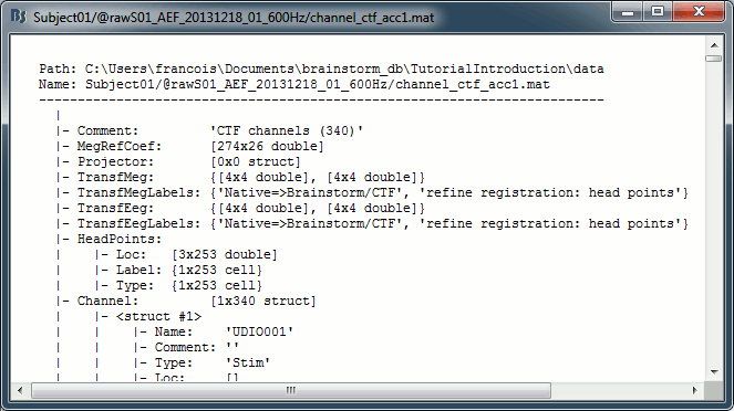
Some other fields are present in the channel file that cannot be accessed with the Channel editor window. You can explore these other fields with the File menu, selecting View file contents or Export to Matlab, as presented in the previous tutorial.
Structure of the channel files: channel_*.mat
Comment : String that is displayed in the Brainstorm database explorer.
MegRefCoef: Noise compensation matrix for CTF and 4D MEG recordings, based on some other sensors that are located far away from the head.
Projector: SSP/ICA projectors used for artifact cleaning purposes. See the SSP tutorial.
TransfMeg / TransfMegLabel: Transformations that were applied to the positions of the MEG sensors to bring them in the Brainstorm coordinate system.
TransfEeg / TransfEegLabel: Same for the position of the EEG electrodes.
HeadPoints: Extra head points that were digitized with a tracking system.
Channel: An array that defines each channel individually (see previous section).
History: Describes all the operations that were performed with Brainstorm on this file. To get a better view of this piece of information, use the menu File > View file history.
IntraElectrodes: Definition of iEEG devices, documented in the SEEG tutorial.
Useful functions
/toolbox/io/import_channel.m: Read a channel file and save it in the database.
/toolbox/io/in_channel_*.m: Low-level functions for reading all the file formats.
/toolbox/io/in_bst_channel.m: Read a channel file saved in the database.
/toolbox/sensors/channel_*.m: Routines for manipulating channel files.
/toolbox/gui/view_channels(ChannelFile, Modality, ...): Display the sensors in a 3D figure.
Additional documentation
Forum: Import the position of SEEG/ECOG contacts: Post #2206, Post #1958, Post #2357

