|
Size: 73195
Comment:
|
Size: 77682
Comment:
|
| Deletions are marked like this. | Additions are marked like this. |
| Line 8: | Line 8: |
| ''Warning: The same tools can be used for processing and displaying ECOG, but this hasn't been debugged properly yet. Please share with us any suggestion for improving the ECOG support.'' |
|
| Line 18: | Line 16: |
| * Go to the [[http://neuroimage.usc.edu/bst/download.php|Download]] page of this website, and download the file: '''tutorial_epimap.zip''' * Unzip it in a folder that is not in any of the Brainstorm folders (program folder or database folder) * Start Brainstorm (Matlab scripts or stand-alone version). * Select the menu File > Create new protocol. Name it "'''TutorialEpimap'''" and select the options: * "'''No, use individual anatomy'''", * "'''No, use one channel file per acquisition run'''". |
* '''SPM''': If you are running Brainstorm from the Matlab environment, for the coregistration between pre- and post-implantation MRI volumes, you need to have the SPM12 toolbox installed on your computer, as a [[https://neuroimage.usc.edu/brainstorm/Tutorials/Plugins|Brainstorm plugin]] or a custom installation. <<BR>>With the stand-alone compiled version of Brainstorm: all the needed SPM scripts have been compiled and included in the executable. * '''Download the dataset''': * Go to the [[http://neuroimage.usc.edu/bst/download.php|Download]] page of this website, and download the file: '''tutorial_epimap.zip''' * Unzip it in a folder that is not in any of the Brainstorm folders (program folder or database folder) * '''Brainstorm''': * Start Brainstorm (Matlab scripts or stand-alone version). * Select the menu File > Create new protocol. Name it "'''TutorialEpimap'''" and select the options: <<BR>>"'''No, use individual anatomy'''",<<BR>>"'''No, use one channel file per acquisition run'''". |
| Line 33: | Line 32: |
| * The MRI viewer opens automatically. Click on "[[http://neuroimage.usc.edu/brainstorm/Tutorials/ImportAnatomy#MNI_transformation|Click here to compute MNI transformation]]". It computes an affine transformation between the subject space and the MNI ICBM152 space, and sets default positions for all the anatomical landmarks.<<BR>> {{attachment:mni_transformation.gif}} | * The MRI viewer opens automatically. Click on "[[http://neuroimage.usc.edu/brainstorm/Tutorials/ImportAnatomy#MNI_normalization|Click here to compute MNI transformation]]". It computes an affine transformation between the subject space and the MNI ICBM152 space, and sets default positions for all the anatomical landmarks.<<BR>> {{attachment:mni_transformation.gif}} |
| Line 45: | Line 44: |
| * Right-click on the pre-implantation MRI > '''SPM canonical surfaces'''. * Leave the default option selected (20484). This represents the resolution of SPM template surface used in this process. The higher the better, but it will slow down significantly the computation of the epileptogenicity maps. * These surfaces will be used later, in the computation of the epileptogenicity maps. Read the advanced sections of this page for information on [[http://neuroimage.usc.edu/brainstorm/Tutorials/Epileptogenicity#Importing_realistic_surfaces|how to use realistic surfaces]] from BrainVISA or FreeSurfer.<<BR>><<BR>> {{attachment:anat_canonical.gif||width="598",height="161"}} |
Note: This tutorial was initially written using SPM canonical surfaces, which are template cortical surfaces that are transformed to the patient space using SPM's [[https://neuroimage.usc.edu/brainstorm/CoordinateSystems#MNI_coordinates|MNI normalization]]. For backward compatibility purposes and for keeping this tutorial simple, we kept using this processing pipeline. However, we later integrated more third-party tools and now recommend generating cortical surfaces with [[http://neuroimage.usc.edu/brainstorm/Tutorials/SegCAT12|CAT12]], especially if you are interested in a realistic representation of the patient's cortical folding in 3D. * In the Process1 tab, do not select any file and click on Run. * Run process: Import > Import anatomy > '''Generate SPM canonical surfaces'''. <<BR>>Select the subject '''Subject01''', and the highest number of verices available ('''20484'''). This number represents the resolution of SPM template surfaces used in this process. The higher the better, but it will slow down significantly the computation of the epileptogenicity maps. <<BR>><<BR>> {{attachment:process_canonical.gif}} {{attachment:anat_canonical.gif}} * These surfaces will be used later, in the computation of the epileptogenicity maps. Read the advanced sections of this page for information on [[http://neuroimage.usc.edu/brainstorm/Tutorials/Epileptogenicity#Importing_realistic_surfaces|how to use realistic surfaces]] from BrainVISA or FreeSurfer. |
| Line 58: | Line 59: |
| In order to generate epileptogenicity maps, we need accurate 3D positions for the contacts of the depth electrodes. Placing the contacts requires a good understanding of the implantation scheme reported by the neurosurgeon, and some skills in reading MRI scans. To make this tutorial easier to reproduce and follow, we distribute the positions of the contacts saved in a text file (folder /anat/implantation). For instructions to place the SEEG contacts using Brainstorm, read the advanced section [[http://neuroimage.usc.edu/brainstorm/Tutorials/Epileptogenicity#Editing_the_contacts_positions|Editing the contacts positions]]. | In order to generate epileptogenicity maps, we need accurate 3D positions for the contacts of the depth electrodes. Placing the contacts requires a good understanding of the implantation scheme reported by the neurosurgeon, and some skills in reading MRI scans. To make this tutorial easier to reproduce and follow, we distribute the positions of the contacts saved in a text file (folder /anat/implantation). For instructions to place the SEEG contacts using Brainstorm, read the advanced section [[http://neuroimage.usc.edu/brainstorm/Tutorials/Epileptogenicity#Edit_the_contacts_positions|Edit the contacts positions]]. |
| Line 73: | Line 74: |
| * If you don't have the positions for the SEEG contacts, or if they don't look correctly aligned, you can directly place them in the MRI viewer. See the section [[http://neuroimage.usc.edu/brainstorm/Tutorials/Epileptogenicity#Editing_the_contacts_positions|Editing the contacts positions]]. | * If you don't have the positions for the SEEG contacts, or if they don't look correctly aligned, you can directly place them in the MRI viewer. See the section [[http://neuroimage.usc.edu/brainstorm/Tutorials/Epileptogenicity#Edit_the_contacts_positions|Edit the contacts positions]]. |
| Line 108: | Line 109: |
| * '''Set skull entry''': Select one electrode in the list, then move the cursor of the MRI viewer to the point where the depth electrode enters the skull, and finally click on [Set skull entry]. This position does not correspond to any contact, it is used only to estimate the direction of the depth electrode. [[http://neuroimage.usc.edu/brainstorm/Tutorials/Epileptogenicity#Editing_the_contacts_positions|More details]]. | * '''Set skull entry''': Select one electrode in the list, then move the cursor of the MRI viewer to the point where the depth electrode enters the skull, and finally click on [Set skull entry]. This position does not correspond to any contact, it is used only to estimate the direction of the depth electrode. [[http://neuroimage.usc.edu/brainstorm/Tutorials/Epileptogenicity#Edit_the_contacts_positions|More details]]. |
| Line 136: | Line 137: |
| === 2D topography === Two additional popup menus allow you to display the SEEG recordings grouped by electrode, but without any 3D information: [[https://neuroimage.usc.edu/brainstorm/Tutorials/ExploreRecordings#A2D_Layout|2DLayout]] and '''2DElectrodes'''. {{attachment:display_2dlayout.gif||width="705",height="199"}} |
|
| Line 233: | Line 239: |
| Starting from this step, you need to have the [[http://www.fil.ion.ucl.ac.uk/spm/software/download/|SPM12 toolbox]] installed on your computer and added to your Matlab path. We need here the multitaper functions from the FieldTrip toolbox, which are also already in the SPM package. | Starting from this step, you need to have the SPM12 toolbox installed on your computer, as a [[https://neuroimage.usc.edu/brainstorm/Tutorials/Plugins|Brainstorm plugin]] or a custom installation. We need here the multitaper functions from the FieldTrip toolbox, which are also packaged in SPM . |
| Line 305: | Line 311: |
| * '''Latency''': 0s<<BR>>List of time points for which we want to compute an epileptogenicity map, with respect to the seizure onset. There is no expected propagation here, we want to study only the first seconds immediately after the onset marker (0-3s). | * '''Latency''': 0s<<BR>>List of time points for which we want to compute an epileptogenicity map (Matlab syntax, "start:step:stop" or "[t1,t2,t3]"), with respect to the seizure onset. There is no expected propagation here, we want to study only the first seconds immediately after the onset marker (0-3s). |
| Line 326: | Line 332: |
| * The delay maps show a summary of the epileptogenicity maps at different time points after the seizure onset. In this example, we computed 11 epileptogenicity maps for SZ2 and SZ3, for sliding windows of 3s (t,,1,,=0-3s, t,,2,,=2-5s, t,,3,,=4-7s, …, t,,11,,=20-23s). These maps of t-statistics were thresholded under a given significance level (p<0.05). If a voxel is significantly activated in the epiptogenicity map at t=t,,i,,, the value for this voxel in the propagation map is t,,i,,, for i=1..11. At the end, the value of each voxel represents the latency for which the activity in this voxel becomes significantly higher than during the baseline. The color bar in the figures below represent the time, from 0 to 20 seconds. <<BR>><<BR>> {{attachment:epilepto_delay_sz23.gif||width="462",height="190"}} | * The delay maps show a summary of the epileptogenicity maps at different time points after the seizure onset. In this example, we computed 11 epileptogenicity maps for SZ2 and SZ3, for sliding windows of 3s (t,,1,,=0-3s, t,,2,,=2-5s, t,,3,,=4-7s, …, t,,11,,=20-23s). These maps of t-statistics were thresholded under a given significance level (p<0.05). If a voxel is significantly activated in the epiptogenicity map at t=t,,i,, ''and'' at t=t,,i+1,,, the value for this voxel in the propagation map is t,,i,,, for i=1..11. At the end, the value of each voxel represents the latency for which the activity in this voxel becomes significantly and continuously higher than during the baseline. The color bar in the figures below represent the time, from 0 to 20 seconds. <<BR>><<BR>> {{attachment:epilepto_delay_sz23.gif||width="462",height="190"}} |
| Line 336: | Line 342: |
| * Add process '''Pre-process > Resample''': 128 Hz, Overwrite<<BR>><<BR>>{{attachment:movie_extract.gif}} * In Process2, select: <<BR>><<BR>>FilesA = Resample seizure recordings '''SZ2_bipolar_2/Onset | time''' (target time definition)<<BR>><<BR>>FilesB = Stat results '''Epileptogenicity_surface/EI_SZ2_120_200_3''' (file that we want to resample) * Run process '''Standardize > Interpolate time''': You can try the interpolation methods "nearest" or "linear", depending on if you would like to see the real statistical results or smooth (but inaccurate) transitions between the steps of two seconds for which the epileptogenicity maps were computed. {{attachment:movie_interp.gif}} * The new resampled epileptogenicity file has the same time definition as the rasampled seizure SEEG recordings: the two can now be opened simultaneously. * After creating all the files you want to display, open them simulateously and position the various figures on your screen the way you would like them to appear in the movie. Note that the text is displayed with a fixed size, it doesn't change if you reduce the size of the figures, so if you make the figures smaller the text will be bigger relatively to the graphics, making it possibly more readable in your screen captures. * To display only a subset of channels in the figure, either use an existing predefined montage, create a montage with the Montage editor, or select the channels you want in the time series figures and use the menu "Create from selection".<<BR>><<BR>>{{attachment:montage_selchan.gif}} * Right-click on any of the figures > Snapshot > '''Movie (time): All figures'''. You can experiment the effect of the various parameters to obtain exactly the movie you want. The figure on which you right-click will show a time stamp at the bottom-left corner in the movie. <<BR>><<BR>> |
* Add process '''Pre-process > Resample''': 128 Hz, Overwrite<<BR>><<BR>> {{attachment:movie_extract.gif||width="569",height="247"}} * Run the execution. The output is a downsampled version of the first 20s after the seizure onset. * In Process2, select: <<BR>>FilesA = Resampled seizure recordings '''SZ2_bipolar_2/Onset | time''' (target time definition)<<BR>>FilesB = Stat results '''Epileptogenicity_surface/EI_SZ2_120_200_3''' (file to resample) * Run process '''Standardize > Interpolate time''': You can try the interpolation methods "nearest" or "linear", depending on if you would like to see the real statistical results or smooth (but inaccurate) transitions between the steps of two seconds for which the epileptogenicity maps were computed. {{attachment:movie_interp.gif||width="642",height="331"}} * The new resampled epileptogenicity file has the same time definition as the resampled seizure SEEG recordings: the two can now be opened simultaneously. * After creating all the files you want to display, open them simultaneously and position the various figures on your screen the way you would like them to appear in the movie. Note that the text is displayed with a fixed size, it doesn't change if you reduce the size of the figures, so if you make the figures smaller the text will be bigger relatively to the graphics, making it possibly more readable in your screen captures. * To display only a subset of channels in the figure, either use an existing predefined montage, create a montage with the Montage editor, or select the channels you want in the time series figures and use the menu "Create from selection".<<BR>><<BR>> {{attachment:movie_selchan.gif||width="628",height="197"}} * Right-click on any of the figures > Snapshot > '''Movie (time): All figures'''. You can experiment the effect of the various parameters to obtain exactly the movie you want. The figure on which you right-click will show a time stamp at the bottom-left corner in the movie. <<BR>><<BR>> {{attachment:movie_create.gif||width="662",height="354"}} * The video file generated can be viewed on any computed, added to a website or included in a slide of a presentation. <<BR>><<BR>> <<HTML(<center><iframe width="560" height="315" src="https://www.youtube.com/embed/1jpmc1Sl6OE" frameborder="0" allow="accelerometer; autoplay; encrypted-media; gyroscope; picture-in-picture" allowfullscreen></iframe></center>)>> <<TAG(Advanced)>> == Video-EEG == EEG recordings and epileptogenicity maps can be reviewed with synchronized video when available. The easier approach is to start by using the clinical EEG software (eg. Micromed BrainQuick) to export the two files for the same time window: the EEG and the video. When the two files are in the same folder with the same name, only with different extensions, they are linked automatically together by Brainstorm. {{attachment:video_link.gif||width="700",height="203"}} If the video is not available in the same folder or has a different name from the EEG file, right-click on the "Link to raw file" > File > '''Add synchronized video'''. On Windows computers, various display options exist thanks to Microsoft ActiveX components. For smooth playback with sound, we recommend you install the '''VLC ActiveX plugin''', available as part of the [[https://www.videolan.org/vlc/download-windows.html|VLC software]]. On Linux and MacOS, only the option "Matlab VideoRenderer" is available, with no sound and no possibility to play the video with a real-time speed (yet). Some EEG-video systems will get automatically synchronized in Brainstorm, other won't. If you notice that the video is not synchronized correctly with the recordings, you need to define manually the delay between the time t=0s in the EEG recordings and the first image of the video. Right-click on the video link > '''Set start time'''. For example, if the EEG recordings start 20s after the beginning of the video, it means that the first image of the video corresponds to time t=-20s, so enter "-20" in the edit box. {{attachment:video_settime.gif||width="408",height="128"}} The videos can be included in the movies created with Brainstorm, such as the one introduced in the previous section. In this case, always prefer the display option "'''Matlab VideoRenderer'''", it will work better in most cases. . {{attachment:video_example.gif}} |
| Line 387: | Line 414: |
| * '''3D''': Sets the positions of the SEEG contacts. In this example, we will load contact positions we obtained from another program, but you could also [[http://neuroimage.usc.edu/brainstorm/Tutorials/Epileptogenicity#Editing_the_contacts_positions|mark the contacts using Brainstorm]]. | * '''3D''': Sets the positions of the SEEG contacts. In this example, we will load contact positions we obtained from another program, but you could also [[http://neuroimage.usc.edu/brainstorm/Tutorials/Epileptogenicity#Edit_the_contacts_positions|mark the contacts using Brainstorm]]. |
| Line 446: | Line 473: |
| Instead of using the default SPM canonical surfaces, you can use realistic cortex envelopes, extracted with [[http://neuroimage.usc.edu/brainstorm/Tutorials/LabelFreeSurfer|FreeSurfer]], [[http://neuroimage.usc.edu/brainstorm/Tutorials/SegBrainSuite|BrainSuite]] or [[http://neuroimage.usc.edu/brainstorm/Tutorials/SegBrainVisa|BrainVISA]]. Instead of importing the anatomy as described previously (pre MRI then post MRI), follow these steps. Note that this cannot be done with the simplified interface in the Guidelines tab. | Instead of using the default SPM canonical surfaces, you can use realistic cortex envelopes, extracted with [[https://neuroimage.usc.edu/brainstorm/Tutorials/SegCAT12|CAT12]], [[http://neuroimage.usc.edu/brainstorm/Tutorials/LabelFreeSurfer|FreeSurfer]], [[http://neuroimage.usc.edu/brainstorm/Tutorials/SegBrainSuite|BrainSuite]] or [[http://neuroimage.usc.edu/brainstorm/Tutorials/SegBrainVisa|BrainVISA]]. Instead of importing the anatomy as described previously (pre MRI then post MRI), follow these steps. Note that this cannot be done with the simplified interface in the Guidelines tab. |
| Line 475: | Line 502: |
| == Editing the contacts positions == | == Edit the contacts positions == |
| Line 491: | Line 518: |
| <<TAG(Advanced)>> == Editing implantation without recordings == |
|
| Line 516: | Line 546: |
| <<TAG(Advanced)>> == Additional documentation == ==== Related tutorials ==== * [[https://neuroimage.usc.edu/brainstorm/Tutorials/Epilepsy|EEG/Epilepsy tutorial]] * [[https://neuroimage.usc.edu/brainstorm/Tutorials/ECoG|ECoG/sEEG tutorial]] <<TAG(Advanced)>> |
SEEG epileptogenicity maps
Authors: Francois Tadel, Olivier David.
This tutorial introduces some concepts that are specific to the management of SEEG recordings in the Brainstorm environment, and explains how to compute maps of epileptogenicity from ictal recordings. It is based on a clinical case from the Grenoble University Hospital, France.
Note that the operations used here are not detailed, the goal of this tutorial is not to introduce Brainstorm to new users. For in-depth explanations of the interface and theoretical foundations, please refer to the introduction tutorials. Another tutorial is available for processing the same dataset with the ImaGIN toolbox.
NOT FOR CLINICAL USE:
The performance characteristics of the methods and software implentation presented in this tutorial have not been certified as medical devices and should be used for research purposes only.
Contents
- Dataset description
- Download and installation
- Import the anatomy
- Access the recordings
- Display the depth electrodes
- Display the SEEG recordings
- Review recordings
- Import epochs of interest
- Time-frequency analysis (pre-onset baseline)
- Time-frequency analysis (separate baseline)
- Epileptogenicity maps
- Video-EEG
- Guidelines panel
- Importing realistic surfaces
- Volume coregistration
- Edit the contacts positions
- Editing implantation without recordings
- On the hard drive
- Additional documentation
- Scripting
Dataset description
License
This tutorial dataset (EEG and MRI data) remains property of the Grenoble University Hospital, France. Its use and transfer outside the ImaGIN and Brainstorm tutorials, e.g. for research purposes, is prohibited without written consent. For questions, please contact Olivier David, PhD ( olivier.david@inserm.fr ).
Clinical description
This dataset includes recordings for a patient that was not reported in the above article, but are part of the same study. The patient presents a focal epilepsy of the left temporo-occipital junction, MRI-negative, and was implanted in the surrounding areas. The subfolder "seeg" contains the recordings of three seizures, all of them showing a propagation of high-frequency oscillations from the lesion towards the temporal lobe, bilaterally.
SEEG recordings
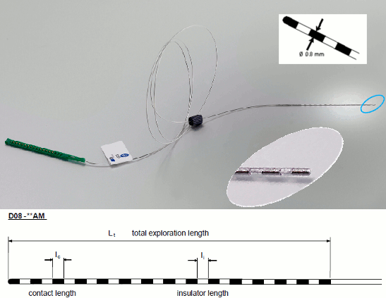
The depth electrodes used in this example dataset are DIXI D08-**AM Microdeep electrodes, with the following specifications:
- Diameter: 0.8 mm
- Contact length: 2 mm
- Insulator length: 1.5 mm
- Distance between the center of two contacts: 3.5 mm
- Between 8 and 18 contacts on each electrode
Files
The dataset we distribute with this tutorial follows the Brain Imaging Data Structure (BIDS) standard for neuroimaging data organization. This specification was first established for MRI and fMRI (Gorgolewski, 2016) and then refined with an extension dedicated to iEEG (Holdgraf, 2019). The files that will be imported in this tutorial are the following:
tutorial_epimap_bids/
derivatives/: Everything that cannot be considered as raw data
brainvisa/sub-01_ses-pre/: Result of the BrainVISA 4.5 segmentation for the pre-implantation T1 MRI.
sub-01/: Raw data for subject 01
ses-preimp/: Imaging exams performed before the implantation of the sEEG.
anat/sub-01_ses-preimp_T1w.nii.gz: T1-weighted MRI pre-implantation
ses-postimp/: Exams performed with the sEEG devices implanted.
anat/sub-01_ses-postimp_T1w.nii.gz: T1-weighted MRI post-implantation
ieeg/..._task-seizure_run-0*_ieeg.eeg: Three seizure recordings in BrainVision file format, one seizure per file (with the header files .vhdr and .vmrk)
ieeg/..._space-IXI549Space_electrodes.tsv: Position of the contacts in MNI space (SPM12 Segment non-linear normalization)
ieeg/..._space-ScanRAS_electrodes.tsv: Position of the contacts in world coordinates, relative to the post-implantation T1 MRI.
All the anatomical images have been de-identified with mri_deface from FreeSurfer 6.
References
The acquisition methodology is described in the following articles:
David O, Blauwblomme T, Job AS, Chabardès S, Hoffmann D, Minotti L, Kahane P, Imaging the seizure onset zone with stereo-electroencephalography, Brain. 2011 Oct;134(10):2898-911
Lamarche F, Job AS, Deman P, Bhattacharjee M, Hoffmann D, Gallazzini-Crépin C, Bouvard S, Minotti L, Kahane P, David O, Correlation of FDG-PET hypometabolism and SEEG epileptogenicity mapping in patients with drug-resistant focal epilepsy, Epilepsia. 2016 Dec; 57(12):2045–2055
Download and installation
Requirements: You have already followed all the introduction tutorials and you have a working copy of Brainstorm installed on your computer.
SPM: If you are running Brainstorm from the Matlab environment, for the coregistration between pre- and post-implantation MRI volumes, you need to have the SPM12 toolbox installed on your computer, as a Brainstorm plugin or a custom installation.
With the stand-alone compiled version of Brainstorm: all the needed SPM scripts have been compiled and included in the executable.Download the dataset:
Go to the Download page of this website, and download the file: tutorial_epimap.zip
- Unzip it in a folder that is not in any of the Brainstorm folders (program folder or database folder)
Brainstorm:
- Start Brainstorm (Matlab scripts or stand-alone version).
Select the menu File > Create new protocol. Name it "TutorialEpimap" and select the options:
"No, use individual anatomy",
"No, use one channel file per acquisition run".
Import the anatomy
Pre-implantation MRI
Right-click on the TutorialEpimap folder > New subject > Subject01.
Keep the default options you defined for the protocol.- Switch to the "anatomy" view of the protocol.
Right-click on the subject node > Import MRI:
Set the file format: "All MRI file (subject space)"
Select the file: tutorial_epimap/anat/MRI/3DT1pre_deface.niiDo you want to apply the transformation to the MRI file? YES
The MRI viewer opens automatically. Click on "Click here to compute MNI transformation". It computes an affine transformation between the subject space and the MNI ICBM152 space, and sets default positions for all the anatomical landmarks.

- Click on [Save] to close the MRI viewer.
Post-implantation MRI
- The pre-implantation MRI will be used as the anatomical reference for this subject. We will now import a second scan done after the SEEG implantation, on which we can see the SEEG contacts. In this dataset, the post-implantation volume is another T1 MRI scan (contacts hyposignal appear in black), but it is more commonly a CT scan (contacts hypersignal appear in white).
Right-click on the subject node > Import MRI:
Select the file: tutorial_epimap/anat/MRI/3DT1post_deface.niiDo you want to apply the transformation to the MRI file? YES
This will reorient the MRI in Brainstorm's standard orientation, so you can see the coronal/sagittal/axial views correctly oriented.How to register the new volume? IGNORE
The two volumes have already been coregistered with SPM. See the section Volume coregistration for more details on this option.Reslice the volume? YES
This will rewrite the volume with the orientation and resolution of the pre-implantation MRI, so that the two volumes can be overlaid in the MRI viewer. You may answer no to this question when the resolution of the pre-implantation MRI is very low and/or when you want to edit the positions of the fiducials in the original post-implantation volume (CT or MRI).The MRI viewer opens automatically, showing the post-implantation volume as a colored layer on top of the previous volume. Adjust the transparency and amplitude threshold of this layer in the section "Data options" of the Surface tab, adjust its colormap with the popup menu of the figure. Use this display to validate that the coregistration of the two volume is correct, all the parts of the head must align well.
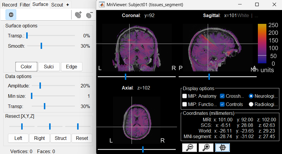
Generate default surfaces
Note: This tutorial was initially written using SPM canonical surfaces, which are template cortical surfaces that are transformed to the patient space using SPM's MNI normalization. For backward compatibility purposes and for keeping this tutorial simple, we kept using this processing pipeline. However, we later integrated more third-party tools and now recommend generating cortical surfaces with CAT12, especially if you are interested in a realistic representation of the patient's cortical folding in 3D.
- In the Process1 tab, do not select any file and click on Run.
Run process: Import > Import anatomy > Generate SPM canonical surfaces.
Select the subject Subject01, and the highest number of verices available (20484). This number represents the resolution of SPM template surfaces used in this process. The higher the better, but it will slow down significantly the computation of the epileptogenicity maps.
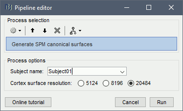
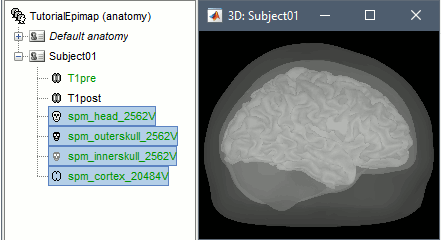
These surfaces will be used later, in the computation of the epileptogenicity maps. Read the advanced sections of this page for information on how to use realistic surfaces from BrainVISA or FreeSurfer.
Access the recordings
Link the recordings
- Switch to the "functional data" view (2nd button, on top of the database explorer).
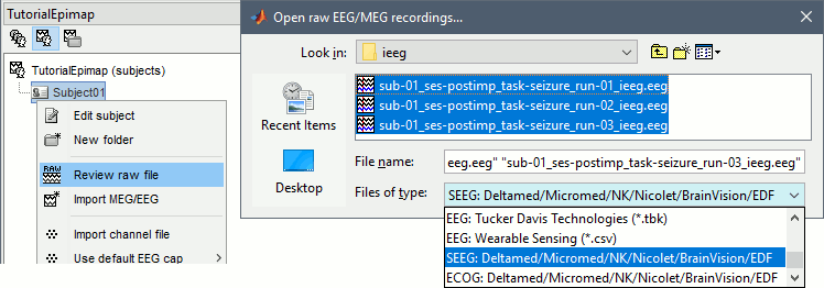
Right-click on the subject folder > Review raw file:
Select the file format: "SEEG: Deltamed/Micromed/..."
Select all the SEEG recordings: tutorial_epimap/seeg/*.TRC
The new files "Link to raw file" let you access directly the contents of the original SEEG files. The menu "Review raw file" does not actually copy any data to the database. More information.
Import the contacts positions
In order to generate epileptogenicity maps, we need accurate 3D positions for the contacts of the depth electrodes. Placing the contacts requires a good understanding of the implantation scheme reported by the neurosurgeon, and some skills in reading MRI scans. To make this tutorial easier to reproduce and follow, we distribute the positions of the contacts saved in a text file (folder /anat/implantation). For instructions to place the SEEG contacts using Brainstorm, read the advanced section Edit the contacts positions.
- The channel files "Micromed channels" contain the name of the channels, but not their positions. We need to import or edit separately the positions of the SEEG contacts.
- Click on the [+] next to the three SZ folders, select all the channel files simultaneously.
Right-click one channel file > Add EEG positions > Import from file:
Select the file format: "EEG: ASCII: Name, XYZ (*.*)"
Select the file: tutorial_epimap/anat/implantation/elec_pos_patient.txt

Select a scaling factor: 0.1 (keep the default selection)
The positions in this text file are in millimeters, while the expected unit for "EEG: ASCII" is the centimeter. This option means that the values will be interpreted as 0.1*cm, ie. millimeters.

Apply MRI transformation? YES
This will interpret the coordinates in the text file as positions in the referential defined by the voxel-to-world transformation (vox2ras) transformation available in the MRI, if applicable (in NIfTI format, this corresponds to matrices qform or sform). If you answer no here, it would load the positions as Brainstorm SCS coordinates and try to realign them based on the NAS/LPA/RPA landmarks.

- At the end, you get a report indicating how many channels from the SEEG recordings were attributed a new 3D position. The channels are matched by name: the position file you import must include the labels of the channels and they must be named exactly in the the same way as in your recordings.
The type of the channels for which a position was not found is set to EEG_NO_LOC, in order to ignore them when processing the SEEG data. In this example dataset, the channels that are not found are "fz" and "cz", which are indeed not SEEG contacts.
You should always validate that the type of all the channels has been detected correctly. Check also that the names are correct and using the same convention for all the contact of a given electrode. These are entered manually, and typing errors are frequent. Right-click on a channel file > Edit channel file.

To edit one channel, double-click on the text to modify. To edit multiple channels, select them all and right-click > Set channel group/type. The column Group corresponds to the name of the depth electrode. It is detected based on the channel type and name. If you include as SEEG a channel that detected as something else or rename a channel, you would need to manually update the channel name.
MNI coordinates: Note that you can also import 3D positions in MNI coordinates. This example dataset includes the MNI coordinates of all the contacts, they are available in the file "elec_pos_patient.txt". To import this file correctly, make sure you select a file format that explicitly mentions MNI coordinates. In this example, it would be: "EEG: ASCII: Name, XYZ_MNI (*.*)".
If you don't have the positions for the SEEG contacts, or if they don't look correctly aligned, you can directly place them in the MRI viewer. See the section Edit the contacts positions.
Display the depth electrodes
3D figures
Right-click on the channel file > Display sensors > Explore all the options available.
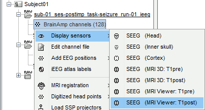
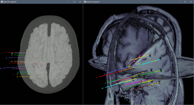
You can render the SEEG depth electrodes in 3D together with the subject anatomy: surfaces, pre- or post-implantation volumes. You can add more anatomy elements to the figure with the button "Add a surface" at the top-right of the Surface tab. For more help: Display the anatomy.
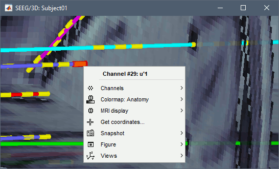
Click on a contact to select it, right-click on it to get its name:
MRI Viewer
You can also display the contacts in the MRI viewer, on top of the the pre- or post-implantation volumes. By default, the electrode is displayed in a slice if there is a SEEG contact associated to it in the slice.
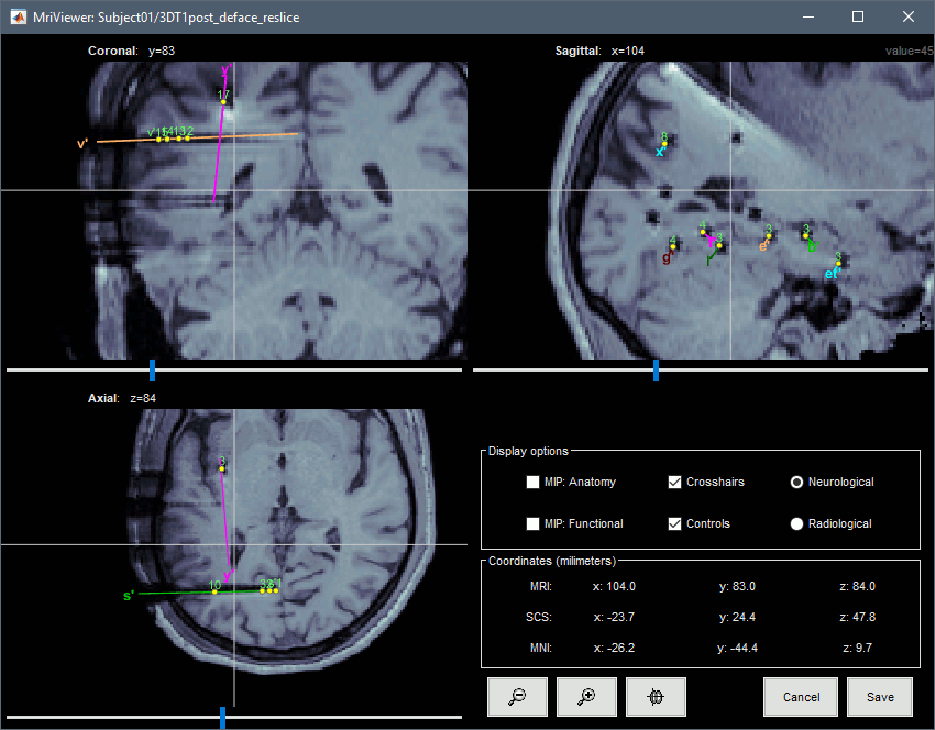
To display all the electrodes, select the option "MIP: Functional". For a glass-brain view, select at the same time the option "MIP: Anatomy".
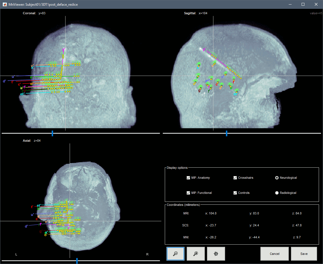
Zoom in/out with the buttons or the associated shortcuts (Ctrl+Scroll or +/-) and explore the volume with (Shift+)x/y/z. Additional display options are available in the popup menu for this figure. All the shortcuts are listed in this tutorial.
You can edit the position of a contact directly by clicking on its dot in one of the slice and moving it around. Modifications are not saved immediately and can be cancelled when you close the window. Alternatively, you can right-click on the figure > Set electrode position.
Panel iEEG
When opening SEEG/ECOG recordings, the panel iEEG is added to the Brainstorm window. You can use it to edit the display properties of the depth electrodes. In this interface, "electrode" refers to entire depth electrode implanted in the head of the patient while "contact" refers to recording sites on the electrode. There are multiple contacts on an electrode, and one contact corresponds to one channel of data in the channel file and the recordings.
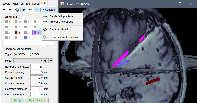
SEEG depth electrodes are graphical objects, they are defined independently from the SEEG contacts available in the channel file and recordings. A contact/channel is associated to a depth electrode using the Group property of the channel, accessible with a right-click on the channel file > Edit channel file.
- In this example, the depth electrodes available in the panel iEEG have been detected automatically based on the names and positions of the data channels. In the convention used here, the contact names must start with one or more letters (the name of the electrode) followed by a number representing the index of the contact on the electrode. Contact #1 is at the tip of the electrode, and is therefore the deeper contact of the electrode. If the convention used in your recordings is different, you may have to edit the electrodes properties in order to get them displayed correctly.
- Buttons in the toolbar:
Add an electrode: Adds an entry for a new depth electrode. The new electrode will not be displayed until you set its properties and position. This will not add or remove SEEG contacts or channels of data.
Remove selected electrodes: Deletes a depth electrode from the list, but does not modify the list of SEEG contacts or channels of data.
Set color for selected electrodes: Self explanatory.
Show/hide selected electrodes: To hide an electrode in the 3D figures and MRI viewer, select it in the list then click on this button. Select all the electrodes with the standard shortcut Ctrl+A.
Display contacts as: Depth electrodes / Spheres.
Contacts > Set default positions: For each of the selected electrodes, the current positions of the SEEG contacts are discarded and replaced with the default positions of the contacts on the electrode. The properties used for setting the position of the contacts are the contact spacing, the tip of the electrode and the entry point in the skull. Contact #i is placed along the electrode at (i-1)*contact_spacing millimeters from the tip of the electrode.
Contacts > Project on electrode: For each of the selected electrodes, the contacts are projected orthogonally on the electrode. This menu can be useful for aligning contacts that were marked one by one.
Contacts > Save modifications: Save the current modifications to the channel file. Otherwise, the modifications are saved only when you close the figure (dialog box "Save modifications to channel file?")
Contacts > Export contacts positions: Save the 3D positions of the SEEG contacts in a text file, using one of the file formats supported by Brainstorm.
Electrode properties: Properties that have an impact on the position of the contacts.
- If you edit the properties, the modifications will apply to all the selected electrodes in the current channel file. Check what is selected before making changes.
Type: SEEG/ECOG
Model: List of electrode models. If you select an entry in this menu, it will copy the default properties for this model to the selected electrodes. If you are using electrodes that are not in this list, please post on the specification of your devices on the user forum and we will add them to this list.
Number of contacts: Number of recording sites on the electrode. By default, this is set for SEEG to the maximum index found in a group of contacts. Example: electrode s' is associated to channels s'1, s'2, s'3, s'10, s'11, s'12 => detected number of contacts is 12.
Contact spacing: Distance between the centers of two consecutive contacts in the electrode. In this example dataset, the default value corresponds to the average distance observed between pairs of adjacent contacts.
Set tip: Select one electrode in the list, then move the cursor of the MRI viewer to the tip of the selected electrode (center of the first contact), and finally click on [Set tip].
Set skull entry: Select one electrode in the list, then move the cursor of the MRI viewer to the point where the depth electrode enters the skull, and finally click on [Set skull entry]. This position does not correspond to any contact, it is used only to estimate the direction of the depth electrode. More details.
- Display options: Properties that only affect the way the electrodes are renderer graphically.
Contact length: Defines the length of the yellow cylinder that represents the contacts along the electrode axis, or the diameter of the sphere when the electrodes are not rendered.
Contact diameter: Diameter of the yellow cylinders representing the contacts. By default, this value is slightly larger than the electrode diameter so that it is rendered correctly. If you use the same value as the electrode diameter, the contacts might not be visible.
Electrode diameter: Diameter of the cylinder representing the SEEG depth electrode.
Electrode length: Length of the cylinder representing the SEEG depth electrode.
Display the SEEG recordings
SEEG time series
Right-click on any "Link to raw file" > SEEG > Display time series.
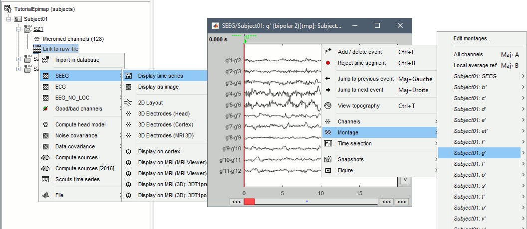
- For instructions on how to use this viewer, please refer to these tutorials:
- Typical display configuration includes:
Set the page duration to 20s or 30s: Record tab > Page settings.
Change the display mode to "columns": Record tab > Toolbar > First button.
Change the montage (bipolar/monopolar): Record tab > Drop-down menu.
Note all the default montages available for SEEG: you can display all the contacts at once, or each electrode individually.- Set visualization filters: Filter tab.
- Disable the automatic scaling when changing page: Button [AS] in the time series figure.
- Adjust the amplitude scale: Right-click+move up/down, or buttons [^] and [v].
Set the resolution precisely: Right-click on the figure > Figure > Set axes resolution.
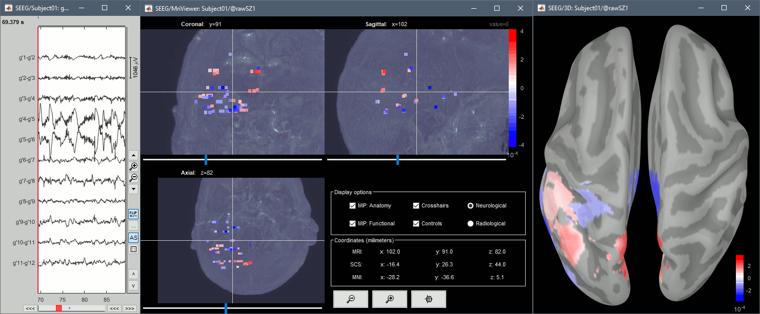
With the menus "3D electrodes" you can visualize the SEEG values at the current time point. Move the time cursor and it will update the values represented on the SEEG contacts.
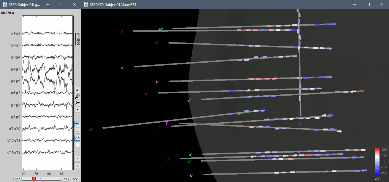
Interpolate on the anatomy
From the same SEEG display menu, you can also project the SEEG values on the MRI or the cortex. You can edit the colormap for the displayed values like any other colormap.
MRI volume: All the voxels in the neighborhood of a contact are attributed the value associated with this contact. In the figure below, both "MIP: functional" and "MIP: anatomy" options are selected (maximum intensity projection along each axis = "glass brain" view).
Cortex surface: The values of the vertices are interpolated from the nearest SEEG contacts (the magnitude decreases with the distance to the contact).
2D topography
Two additional popup menus allow you to display the SEEG recordings grouped by electrode, but without any 3D information: 2DLayout and 2DElectrodes.

Review recordings
Power spectrum
We recommend you always start your data analysis with a spectral evalution of the recordings, it may help you identify bad channels. This is described in tutorials Power spectrum and EEG and epilepsy.
- In Process1, select all the continuous files (SZ1, SZ2, SZ3: link to raw files or folders).
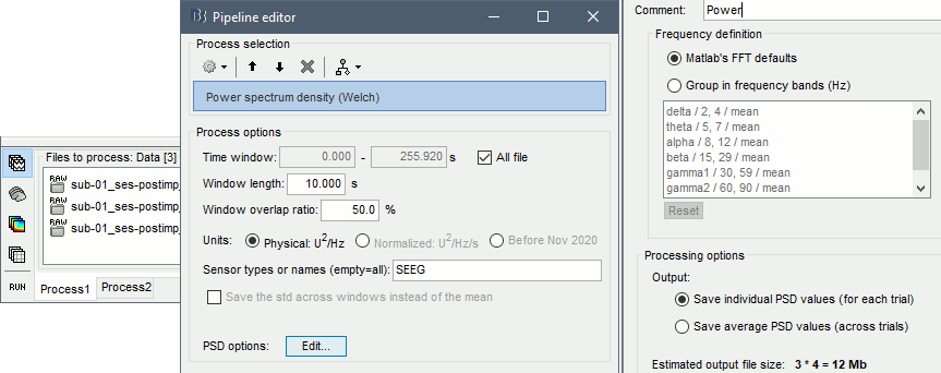
Run process Frequency > Power spectrum density (Welch): All file, Length=10s, Overlap=50%.
Double-click on the PSD files to display them. Some channels have noise levels that are obviously higher than the others and should therefore be considered as suspicious.
Left = SZ1 (v'1,f'1), Center = SZ2 (v'1,t'8), Right = SZ3 (o'1,t'8)
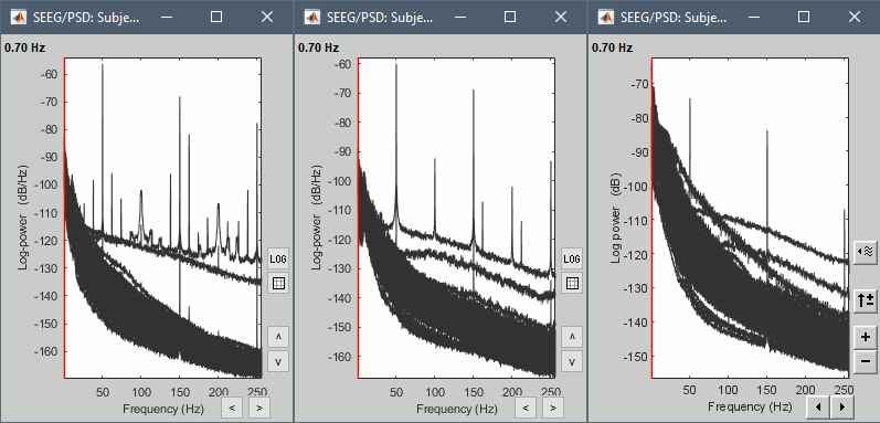
- If the spectrum plots are too noisy and difficult to read, you can recompute them with lower frequency resolution. Decrease the duration of the estimator window, possibly down to 1s depending on the sampling frequency. This will estimate the PSD by averaging the power of more time windows with less data bins, the result will be smoother.
Bad channels
We will now to review the recordings of the three seizures recorded for this subject: SZ1, SZ2, SZ3. All the following steps are illustrated only for SZ1 but need to be reproduced for the other files.
Double-click on SZ1/Link to raw file to open the SEEG recordings for the first seizure.
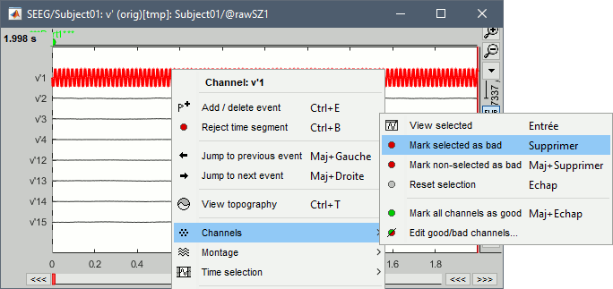
We need to mark the bad channels using a "monopolar" montage (common reference). If you are currently reviewing the recordings with a bipolar montage, switch it back to "All channels", using the menu in the toolbar of the record tab or with the popup menu of the time series figure. Otherwise, marking a signal as bad (eg. "v'2-v'1") would actually mark two channels as bad ("v'1" and "v'2"), while only one contact ("v'1") is not recording properly.
Click on the channels that you consider as bad to select them. For SZ1, select v'1 and f'1.
Press the delete key, or use the popup menu Channels > Mark selected as bad.
- Close the figure and repeat for the two other files.
- Bad channels for the three seizures:
SZ1: v'1, f'1
SZ2: v'1, t'8
SZ3: o'1, t'8
Seizure onset
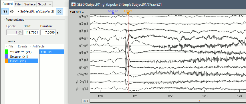
Two events are already available in this file: "Part1" only indicates the beginning of the file, and "Seizure" indicates approximately the onset of the first seizure. This marking was done for clinical use, to jump quickly to the page of interest, but here we need a more accurate marker. We will create a new marker "Onset" where we observe the beginning of the fast gamma activity, which is the main feature used in the computation of the epileptogenicity maps.
Double-click on SZ1/Link to raw file to open the SEEG recordings for the first seizure, or do this immediately after marking the bad channels.
Switch to a bipolar montage: bipolar-1 is sparse (eg. g1-g2, g3-4), bipolar-2 is exhaustive (eg. g1-g2, g2-g3, g3-4), depending on how dense you want your figure to be.
In the Record tab, click on the event group "Seizure", then on the event timing. This will jump quickly to the page on which we will place our Onset marker.
Zoom around the g' contacts (using the buttons on the right of the figure or the corresponding shortcuts, indicated if you leave your mouse over the buttons for a second), or select the g' electrode in the montage menu.
- If needed, zoom locally in time in the current page (mouse wheel) and change the amplitude scale (right-click+mouse up/down).
Create an event group "Onset": Record tab > Events > Add group > "Onset".
Place the time cursor at 120.800s, add an Onset marker at this time (press the key "E", or use the popup menu Add/delete event).
If you are marking a lot of events, you might be interest in using custom shortcuts.
- Repeat for the other files. Seizure onset time for the three seizures:
SZ1: 120.800s
SZ2: 143.510s
SZ3: 120.287s
Baseline
In the following sections, we will compute a time-frequency decomposition of the seizure and normalize it with respect to a baseline level. We will identify and import this baseline now. The baseline could be a segment of 5s to 30s of recordings, typically before the seizure, that contains as little interictal epileptiform activity as possible.
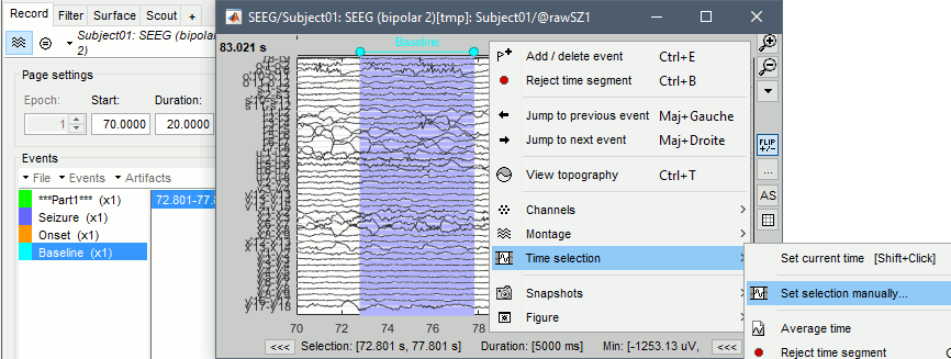
The duration of the baseline influences the computation time for the following steps of this tutorial. We will work here with short segments of 5s for illustration purposes, between 72.8s and 77.8s. Use longer segments for more accurate results.
Create a new event group "Baseline".
Select the segment [72.8s, 77.8s]: Click and drag your mouse, or right-click > Time selection > Set selection manually. Then create a Baseline extended event ("E" or "Add/delete event").
- Repeat for the other files. Baselines for the three seizures:
SZ1: [72.800, 77.800]s
SZ2: [103.510, 108.510]s
SZ3: [45.287, 50.287]s
Close the viewer to save the modifications, or use the menu File > Save modifications.
Import epochs of interest
At this point of the analysis, we are still looking at the original files, no SEEG data was copied to the database. The montages are saved in the Brainstorm preferences, the bad channels and new events are saved in the links of the database but not reported to the original .TRC files. If you delete your protocol at this point, you would only lose the event marking and bad channel selection.
We are now going to import two segments of recordings for each seizure file: the seizure (10s before and 40s after the onset) and the baseline (all the segment selected). This will make real copies of the data in the database, so we can run additional processes on them.
Import in database
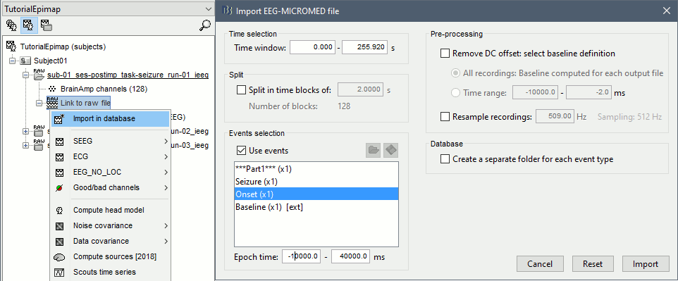
Right-click on SZ1 / Link to raw file > Import in database:
- Time window: All, the only interesting point is to have access to the Onset marker.
- Split in time blocks: Disabled
Use events: Enabled, select Onset
Epoch time: [-10000, +40000] ms (imports -10s to 40s around the event "Onset")
- Remove DC offset: Disabled
- Resample: Disabled
Create a separate folder for each event type: Disabled
- Repeat the last operation to import the baseline, modify only the following options:
Use events: Select Baseline
- Epoch time: Not applicable, the event Baseline already defines a start and an end.
- Repeat for the three seizures.
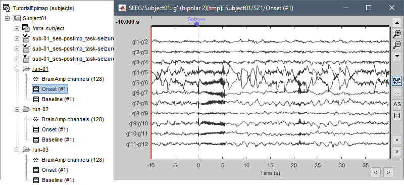
- At the end, you should have three new folders SZ1/SZ2/SZ3, the same name as the original .TRC files, but without the tag "raw" on top. These new folders contain copies of the SEEG recordings, if you delete these folders from the database explorer, you lose the recordings they contain.
The imported epochs are saved with a new timing: for the seizure onsets, the reference time t=0s is now the event "Onset", which has been removed from the list. You can still see the other marker Seizure, which should be slightly before 0s. For the baselines, the reference t=0 is the beginning of the segment.
Bipolar montage
We will run the rest of the analysis using a bipolar montage (bipolar-2). The montage selected in the Record tab is for visualization only, most processes ignore this selection and work only on the original common-reference data. To force all the processes to work on the bipolar values, we need to explicitly apply the montage to the recordings.
- In Process1, drag and drop all the imported recordings (either the folders or the files).
Run the process Standardize > Apply montage:
Montage name: Subject01: SEEG (bipolar 2)
Create new folders: Enabled
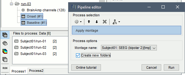
This process rewrites the channel files and data files in the selected folders. The position associated with a bipolar channel in the channel file is the middle of the segment between the two contacts (eg. "b'1-b'2" is placed half-way between "b'1" and "b'2").
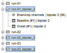

- If you display these new recordings and select the montage "All channels", it would now show the bipolar values. If you select a bipolar montage for these new files, it would do something you don't want, such as displaying values like "(b'1-b'2)-(b'2-b'3)".
Uniform list of channels
In this example dataset, the list of channels recorded for all the files is the same, we can directly process the three seizures together. But this is not always the case, the list of recorded channels might be different between two files. This could happen if the patient was implanted multiple times, or if not all the contacts could be recorded simultaneously due to technical limitations related with the amplifiers or the acquisition software.
For files that have different channels recorded, or the same contacts in a different order, you need to chose one of the two following approaches:
Process the two files separately: the differences will not matter, but you would obtain one epileptogenicity map for each file instead of a group result.
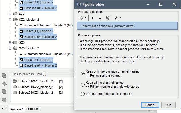
Process the two files together: in this case, only the contact names that are found in all the input files are kept. All the other contacts are removed from the channel files and the recordings files. This will allow the computation of possibly more stable group results, but at the cost of ignoring some of the data. This approach is acceptable only if the deleted channels are far from the seizure onset zone, or you already know they are not associated with any interesting observation.
If you choose the second option, you need to call a process that deletes the unwanted channels. Select all the bipolar files (Onset and Baseline) in Process1, and run the process Standardize > Uniform list of channels, with the option "Keep only the common channel names".
Time-frequency analysis (pre-onset baseline)
The aim of this section is to evaluate the frequency range for the computation of the epileptogenicity maps. We need to identify which frequency band is the most representation and specific of the high-frequency activity at the beginning of the seizures.
Starting from this step, you need to have the SPM12 toolbox installed on your computer, as a Brainstorm plugin or a custom installation. We need here the multitaper functions from the FieldTrip toolbox, which are also packaged in SPM .
- In Process1, select all the Onset bipolar files.
Select the process: Frequency > FieldTrip: ft_mtmconvol (Multitaper): (do not run)
Time window: [-10, 10]s
Sensor types: SEEG
Taper: hanning
Frequencies: 10:3:220
Modulation factor: 10
Time resolution: 1000ms
Measure: Magnitude
Save average: Disabled
Add the process: Standardize > Baseline normalization:
Baseline: [-10, -1]s
Method: Z-score transformation
Overwrite: Enabled
Add the process: Average > Average files:
Group files: Everything
Function: Arithmetic average
Run the pipeline.
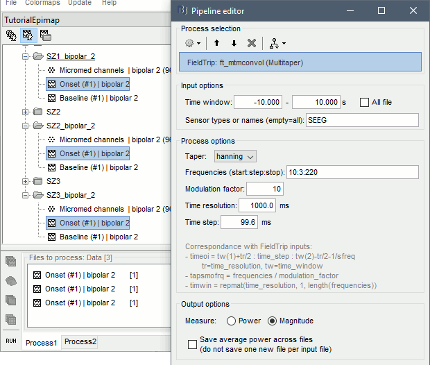
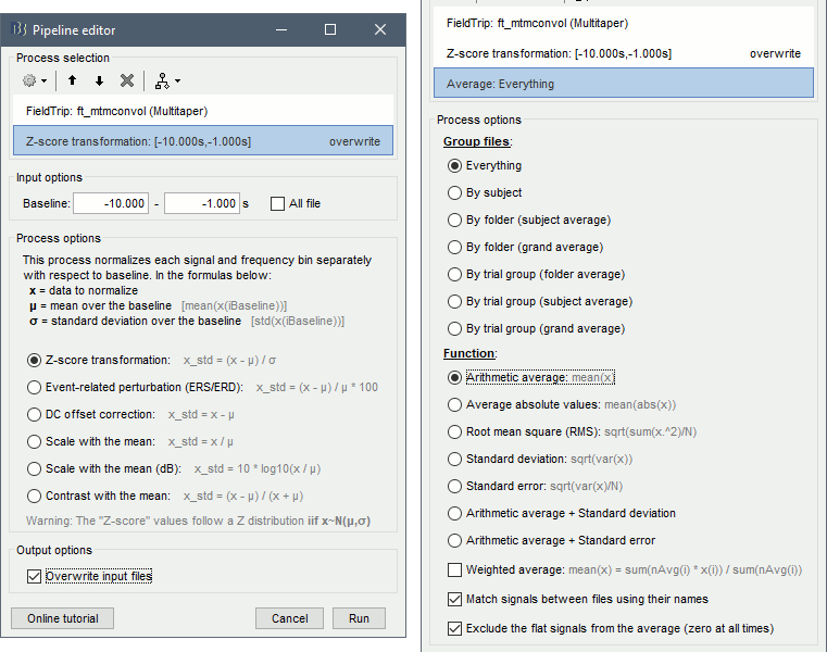
- Four new files are available in the database: one for each bipolar Onset epoch, and one average, saved in folder "Intra-subject".
Right-click on the average time-frequency map > All channels. Then you can click on a channel to open it in a separate figure. Change the colormap to "GIN" and the colormap maximum to [-0.1,+0.1]*10^2 to reproduce the figures below.
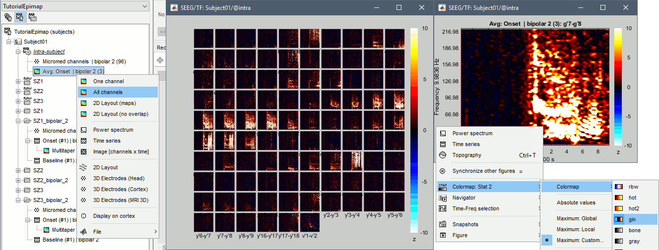
- These figures are useful to identify a frequency band specific of the fast rhythmic activity after the seizure onset. To create the epileptogenicity maps in the next tutorial, we will use a frequency band for which we observe a significant increase after t=0 with the highest possible frequencies. The underlying physiological hypothesis is that the frequency is higher close to the seizure onset zone, and decreases with the propagation: the highest the frequency, the highest the spatial specificity.
Our goal is to identify a few contacts, among the ones showing a sustained significant activity after t=0, for which the power increases in higher frequencies than the others. As a guideline to what is significant and what is not: the values represented here are Z-scores, and a value of Z=5 is already very significant. You can increase the saturation of the image by setting manually the highest value in the color bar (colormap configuration).
Example of two signals, the first one possibly very close to the seizure onset zone (g'7-g'8), and the second one a bit further away (c'9-c'10). This observation leads us to consider the frequency band from 120Hz to 200Hz (represented in green).

Time-frequency analysis (separate baseline)
Another approach is to normalize the time-frequency maps based on the baseline file used for the computation of the epileptogenicity maps, instead of the short baseline immediately before the seizure onset. This is a bit more complicated but produces maps that are more coherent with the epileptogenicity measures used in the next section. To increase the educational value of this section, let's manage the time differently: we'll compute the time-frequency decomposition for the entire Onset epochs (-10s,+40s) and then extract only the section we are interested in.
Start by deleting all the time-frequency files computed in the previous section: select them in the database explorer and press the Delete key, or select the subject folder in Process1 with button [Process time-freq] selected and use process File > Delete files > Delete selected files.
- In Process1, select all the bipolar files (Onset and Baseline).
Run the process: Frequency > FieldTrip: ft_mtmconvol (Multitaper):
Time window: All file
Sensor types: SEEG
Taper: hanning
Frequencies: 10:3:220
Modulation factor: 10
Time resolution: 1000ms
Measure: Magnitude
Save average: Disabled
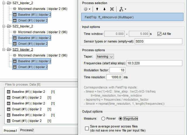
- In Process2, select the time-frequency file for the baseline in FilesA, and for the onset in FilesB. You can either select the time-domain epochs and click on the buttons [Process time-freq], or select directly the time-frequency files generated with the previous step. Note the order in these lists matters: make sure you select the Onset and Baseline files in the exact same order.
Select the process: Standardize > Baseline normalization (do not run immediately):
Baseline: All file
Method: Z-score transformation
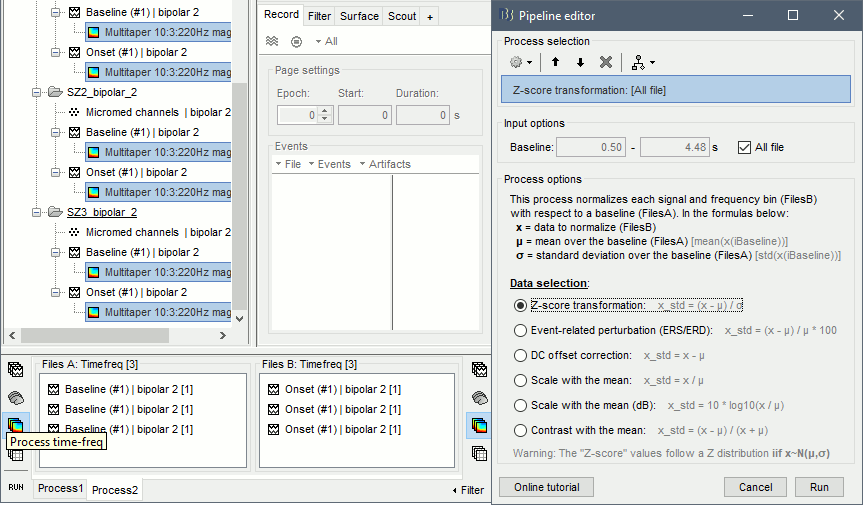
Add process: Average > Average files:
Group files: Everything
Function: Arithmetic average
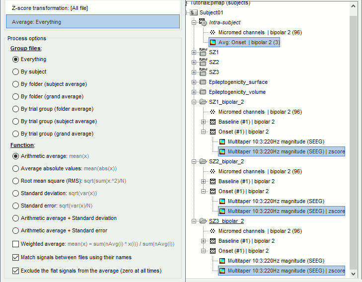
Run the pipeline. In output, you get the three normalized time-frequency maps for the three Onset epochs, plus the average of these three files. As expected, the time definition of the average file is [-10,+40]s. In order to produce similar figures as the ones from the previous section, we will extract the same time window as before (-10s to +10s).

- In Process1, select the average time-frequency map.
Run process Extract > Extract time, time window = [-9.5, 9.53]s (FieldTrip's multitaper function cuts a piece of the recordings to account for possible edge effects).
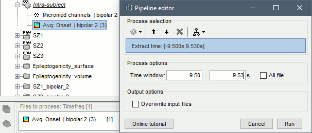
If the observations you make are very different from the previous sections, it means that the brain activity is different in the two baselines. Figures below show bipolar channel g'7-g'8: left=10s immediately before the seizure (previous section), right=baseline selected somewhere else in the file (this section).

Epileptogenicity maps
The goal of this section is to create 3D maps of epileptogenicity, with the expectation they indicate the location and extent of the seizure onset zone, and maps of propagation delay in the patient's brain. The method used for computing the epileptogenicity maps is described in this article:
David O, Blauwblomme T, Job AS, Chabardès S, Hoffmann D, Minotti L, Kahane P, Imaging the seizure onset zone with stereo-electroencephalography, Brain, 2011
The first seizure is short (around 5s), without any propagation. We will first compute the epileptogenicity map for this one, without any delay map. Then we will process seizures #2 and #3 together, with the associated delay maps during the first 20s of the seizure.
We can compute and display the results either in the full MRI volume, or only limited to the cortex surface. To illustrate the two approaches, we will run the first example (seizure #1) in the volume, and the second example (seizure #2 and #3) on the surface. This choice is arbitrary and for demonstration purpose only. If you decide for one approach (volume or surface), keep the same choice for all your analyses.
Volume: Seizure 1
In Process2, select the following files:
FilesA = SZ1_bipolar_2/Baseline, FilesB = SZ1_bipolar_2/OnsetRun process: Epilepsy > Epilepogenicity maps
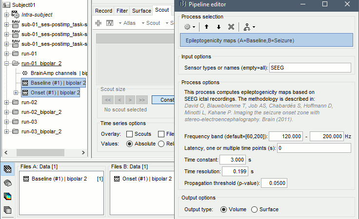
Sensor types: SEEG
Frequency band: 120-200 Hz
Frequency band specific of the beginning of the seizure, which should be adapted for each subject manually. See previous section.Latency: 0s
List of time points for which we want to compute an epileptogenicity map (Matlab syntax, "start:step:stop" or "[t1,t2,t3]"), with respect to the seizure onset. There is no expected propagation here, we want to study only the first seconds immediately after the onset marker (0-3s).Time constant: 3s
Duration of the time window used to estimate the epileptogenicity map.Time-resolution: 0.2s
Each 3s window is subdivided in small blocks of 0.2s, the power in each block is estimated for the frequency band 120-200Hz, and a t-test is performed with SPM for all the 0.2s blocks in the baseline vs. all the 0.2s blocks in the time window of interest (post-onset). The result of this t-test is the epileptogenicity map.Propagation threshold: 0.05
Related to the computation of the delay map, so not applicable here. The epileptogenicity maps computed for each 3s window are thresholded using this threshold, then grouped into one single delay map. If the value is <1, it is interpreted as a p-value, otherwise it is interpreted as a T-value threshold.Output type: Volume
The results are saved in a new folder "Epileptogenicity_volume" containing three files:
- The channel file is a copy of the channel file in folder SZ1_bipolar_2.
- The "source" file contains the epileptogenicity maps and can be displayed in the volume.
- The "recordings" file contains the epileptogenicity index estimated for each bipolar contact.
- These files are time resolved when the "Latency" option is a vector. This will be illustrated in the next section. In this example, if you double-click on the sensor data, you get to see only flat lines because there is only one time point.
Display the two files in various ways and explore the results. From the Stat tab, edit the statistical threshold and the type of correction for multiple comparisons.
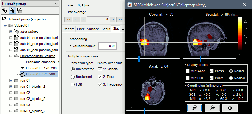
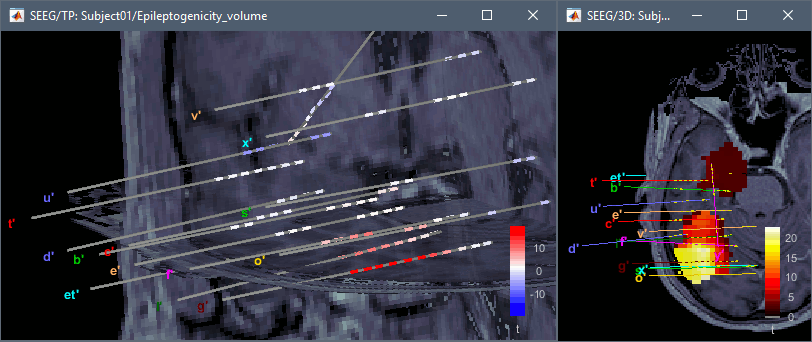
Note for the SPM experts: If you are interested in exploring all the files generated by SPM, you can access them immediately after the execution in the temporary folder $HOME/.brainstorm/tmp/ImaGIN_epileptogenicity.
Surface: Seizure 2/3
In Process2, select the following files:
FilesA = SZ2_bipolar_2/Baseline and SZ3_bipolar_2/Baseline
FilesB = SZ2_bipolar_2/Onset and SZ3_bipolar_2/OnsetRun process: Epilepsy > Epilepogenicity maps
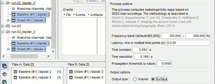
Latency: 0:2:20 s
Computes the epileptogenicity maps for sliding windows of 3s between 0s and 20s post-seizure (ie. 0-3s, 2-5s, 4-7s, 20-23s…), then summarizes these results in delay maps with a 2s resolution.Output type: Surface
We obtain 9 files in a new folder Epileptogenicity_surface: 3x epileptogenicity index (sensor level), 3x epileptogenicity maps (volume), 3x delay maps. For each type of file, we have one result for each individual seizure (_SZ2_*, _SZ3_*) and one for the group results, ie. the two seizures processed simultaneously (_Group_*).
This time, if you double-click on the sensor data, you will observe time series corresponding to the evolution of the epileptogenicity index for each bipolar contact. This seems to show a propagation from electrode g' to electrode et'.
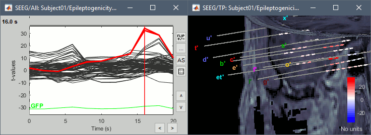
The epileptogenity maps are now time-resolved as well. Move the time cursor in the time series figure and it updates the maps in all the other figures. You can create the figures below with the popup menu Snapshot > Time contact sheet.
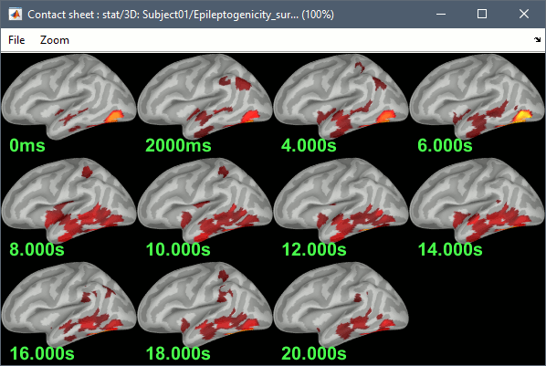
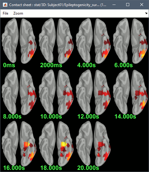
The delay maps show a summary of the epileptogenicity maps at different time points after the seizure onset. In this example, we computed 11 epileptogenicity maps for SZ2 and SZ3, for sliding windows of 3s (t1=0-3s, t2=2-5s, t3=4-7s, …, t11=20-23s). These maps of t-statistics were thresholded under a given significance level (p<0.05). If a voxel is significantly activated in the epiptogenicity map at t=ti and at t=ti+1, the value for this voxel in the propagation map is ti, for i=1..11. At the end, the value of each voxel represents the latency for which the activity in this voxel becomes significantly and continuously higher than during the baseline. The color bar in the figures below represent the time, from 0 to 20 seconds.
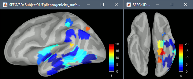
If the colormap does not go up to the maximum time point (eg. 16s or 18s), it can be either because there is nothing significant in the last latencies (not very plausible here) or because all the significant values at t=20s were also significant at earlier latencies. To force the colormap to go from 0s to 20s, edit its properties (right-click on the figure > Colormap > Maximum: Custom).
Create a movie with the SEEG signals
Saving the conclusions of your visual exploration as a video file is an efficient solution for keeping track of your analyses and sharing them with your colleagues. In such a movie, it can be interesting to display simultaneously the original SEEG recordings with the epileptogenicity maps. However, if you try to open the two files, you get an error message explaining that Brainstorm cannot display two files with different time definitions at the same time.
A solution to go around this limitation is to resample the epileptogenicity results (one value every two seconds = 0.5Hz) with the same frequency as the SEEG recordings (initially 512Hz). This would multiply the size of the file containing the epileptogenicity results by 2*512, creating a file of several Gb. To avoid wasting too much disk space and risking to crash Matlab by creating gigantic variables, we can cut and downsample the SEEG recordings of interest. Let's illustrate this with the seizure SZ2.
In Process1, select the file SZ2_bipolar_2/Onset.
Select process Extract > Extract time: 0-20 s
Add process Pre-process > Resample: 128 Hz, Overwrite
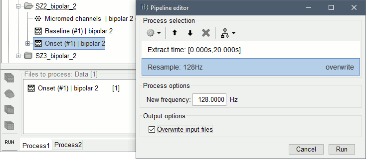
- Run the execution. The output is a downsampled version of the first 20s after the seizure onset.
In Process2, select:
FilesA = Resampled seizure recordings SZ2_bipolar_2/Onset | time (target time definition)
FilesB = Stat results Epileptogenicity_surface/EI_SZ2_120_200_3 (file to resample)Run process Standardize > Interpolate time: You can try the interpolation methods "nearest" or "linear", depending on if you would like to see the real statistical results or smooth (but inaccurate) transitions between the steps of two seconds for which the epileptogenicity maps were computed.
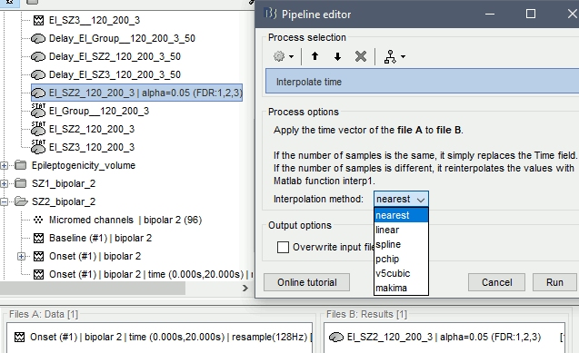
- The new resampled epileptogenicity file has the same time definition as the resampled seizure SEEG recordings: the two can now be opened simultaneously.
- After creating all the files you want to display, open them simultaneously and position the various figures on your screen the way you would like them to appear in the movie. Note that the text is displayed with a fixed size, it doesn't change if you reduce the size of the figures, so if you make the figures smaller the text will be bigger relatively to the graphics, making it possibly more readable in your screen captures.
To display only a subset of channels in the figure, either use an existing predefined montage, create a montage with the Montage editor, or select the channels you want in the time series figures and use the menu "Create from selection".

Right-click on any of the figures > Snapshot > Movie (time): All figures. You can experiment the effect of the various parameters to obtain exactly the movie you want. The figure on which you right-click will show a time stamp at the bottom-left corner in the movie.
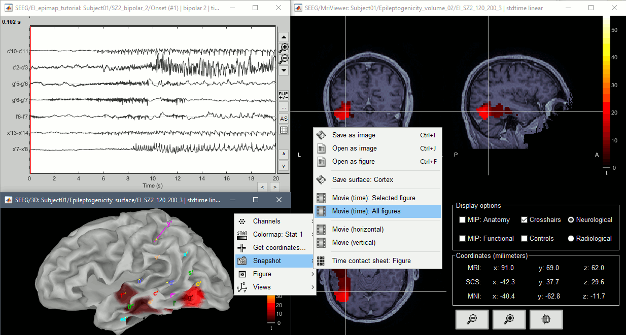
The video file generated can be viewed on any computed, added to a website or included in a slide of a presentation.
Video-EEG
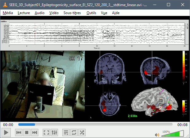
EEG recordings and epileptogenicity maps can be reviewed with synchronized video when available. The easier approach is to start by using the clinical EEG software (eg. Micromed BrainQuick) to export the two files for the same time window: the EEG and the video. When the two files are in the same folder with the same name, only with different extensions, they are linked automatically together by Brainstorm.

If the video is not available in the same folder or has a different name from the EEG file, right-click on the "Link to raw file" > File > Add synchronized video.
On Windows computers, various display options exist thanks to Microsoft ActiveX components. For smooth playback with sound, we recommend you install the VLC ActiveX plugin, available as part of the VLC software. On Linux and MacOS, only the option "Matlab VideoRenderer" is available, with no sound and no possibility to play the video with a real-time speed (yet).
Some EEG-video systems will get automatically synchronized in Brainstorm, other won't. If you notice that the video is not synchronized correctly with the recordings, you need to define manually the delay between the time t=0s in the EEG recordings and the first image of the video. Right-click on the video link > Set start time. For example, if the EEG recordings start 20s after the beginning of the video, it means that the first image of the video corresponds to time t=-20s, so enter "-20" in the edit box.

The videos can be included in the movies created with Brainstorm, such as the one introduced in the previous section. In this case, always prefer the display option "Matlab VideoRenderer", it will work better in most cases.
Guidelines panel
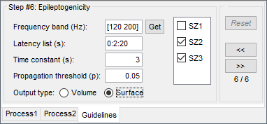
In addition to this process "Epileptogenicity maps", we developped a simpler interface to reproduce the same analysis with fewer interface manipulations.
In the Brainstorm window, select the menu Help > Guidelines > Epileptogenicity maps. It opens a new panel at the bottom of the Brainstorm window. You can work with a mix of controls from this panel and the regular database explorer.
Click on [>>] to move to the next step, and [Reset] to restart the analysis from this step for the selected subject. The first step (1/6) is an introduction, nothing happens here.
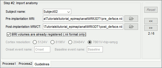
Step 2: Import anatomy
Edit the mandatory inputs:
Subject name: Type "Subject02", it will create a new subject in the same protocol. We will import the same anatomy and recordings as in Subject01, it will allow us to compare the files obtained with the two methods. Later, when opening again the Guidelines panel, simply select an existing subject to resume the analysis where you left it.
Pre-implantation MRI: Select tutorial_epimap/anat/MRI/3DT1pre_deface.nii
Post-implantation MRI/CT: Select tutorial_epimap/anat/MRI/3DT1post_deface.nii
MRI volumes are already registered: Enabled.
When this option is not selected, Brainstorm calls SPM to coregister the pre- and post-implantation volumes. If the volumes have already been coregistered and the .nii files look correctly aligned in any other program, leave this option unchecked to use the existing registration, it will save some time when importing the files.
Ignore the advanced options, keep the default values:
Cortex resolution: This defines which cortex surface will be used to compute the interpolation between the SEEG contacts and the MRI volume. The first three options (5124V, 8196V, 20484V) correspond to the options available for the computation of the SPM canonical mesh of the cortex, the number indicates the number of vertices of the surface. The last one (7861V+hip+amyg) is a modified version of SPM8 canonical mesh with extra vertices to represent the hippocampus and the amygdala of both hemispheres, which was used in the reference publication for the epileptogenicity maps.
Onset event name: Name of the event representing the seizure onset in the recordings.
Baseline event name: Name of the event representing the baseline in the recordings.
Click on [>>] to validate this step and import the anatomy.
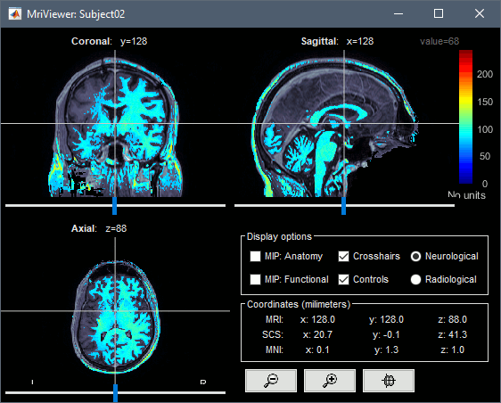
The MRI viewer opens automatically, showing the post-implantation volume as a colored layer on top of the pre- volume. Adjust the transparency and amplitude threshold of this layer in the section "Data options" of the Surface tab, adjust its colormap with the popup menu of the figure. Use this display to validate that the coregistration of the two volume is correct, all the parts of the head must align well.
Step 3: Prepare recordings
Use this panel to include the seizure recordings in the database, set the 3D positions of the SEEG contacts, exclude bad channels and mark onset and baseline events. The documentation below explains the role of each button in the toolbar.
Add files: Click on the first button ("Add ictal recordings for this subject")
Select the file format: "SEEG: Deltamed/Micromed/..."
Select all the SEEG recordings: tutorial_epimap/seeg/SZ*.TRC
After adding the files to the database, the channel editor is opened automatically. This corresponds to clicking on button [Channels], see below.

Channels: Opens the channel editor to edit the properties of all the channels of data that were recorded in the .TRC files. The column "#" in the Guidelines tab indicates the number of SEEG channels detected in each file. Make sure the names and types are correct for all the channels.
To edit one channel, double-click on the text to modify. To edit multiple channels, select them all and right-click > Set channel group/type.
The column Group corresponds to the name of the depth electrode. It is detected based on the channel type and name. If you include as SEEG a channel that was detected as something else or rename a channel, you would need to manually update the channel group.

- If you modify the list of channels associated to the type "SEEG", when you close the channel editor and save the modifications, the number of SEEG contacts in the Guidelines tab should be updated automatically.
Note that the Guidelines tab gets updated automatically only for operations that were initiated from the Guidelines tab. If you open the channel editor from the database explorer and modify the list of SEEG channels, the number in the column "#" would not be updated automatically. The same goes for the bad channels and event markers. To force the values in the Guidelines tab to be reloaded, click [<<] and [>>] again.
- If all the files have the same list of channels (same names and same order), the modifications done for one file are reported to all the other channel files. Otherwise, it saves only the modifications for the file that was selected before clicking on [Channels]. If the channel list is different across files, you have to edit the channel file separatly for each file (select the file in the list, then click on [Channels]).
3D: Sets the positions of the SEEG contacts. In this example, we will load contact positions we obtained from another program, but you could also mark the contacts using Brainstorm.
Click on [3D], then [Import]
Select file format: "EEG: ASCII: Name, XYZ (*.*)"
Select file: tutorial_epimap/anat/implantation/elec_pos_patient.txt
Select default options: [0.1] and [Yes]. More details.
After importing the positions, a 3D figure shows the post-implantation volume with the imported contacts positions, and possibly the depth electrodes if the detection worked well. Move the volume slices to make sure the contact artifacts match the positions of the electrodes.
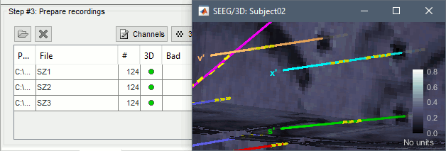
The circles in the column "3D" of the Guidelines tab turn green when the 3D positions of all the SEEG contacts is set. If it stays red after importing the positions, you have either some channels mislabelled as SEEG, or a list of positions that does not include all the SEEG contacts. Another common issue is the use of a different labelling convention in the SEEG recordings and the file with the positions. You may have to rename the contacts either in the channel file (from Brainstorm) or in the positions file (with a text editor, before importing) in order to have them matched correctly.
- Same comment as for the button [Channels]: If all the files have the same list of channels (same names and same order), the modifications done for one file are reported to all the other channel files. Otherwise, it saves only the modifications for the file that was selected before clicking on [3D].
Review: Displays the SEEG recordings for the selected file. The goal is now to mark for each file: the bad channels, the seizure onset(s), the baseline(s).
- Select the first file SZ1, click on [Review] (or simply double-click on the first file).
Use a monopolar montage, then mark the bad channels.
If you close the figure, it saves the modifications and updates the panel.

Onset: Adds an event marker "Onset" to identify the seizure onset. The marker is placed at the current time (red cursor in the figure). If the file viewer is not opened yet, this button has the same effect as the button [Review].
Follow these recommendations for selecting an appropriate seizure onset.
- When you close the figure, it saves the modifications and updates the panel. But you don't have to close and save at each step: mark the bad channels, onset and baseline markers for a file before closing.
If you already know the bad channels/onset/baseline for a file, right-click on the file and select the appropriate menu.
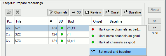
Baseline: Adds an event marker "Baseline" in the file. The baseline must be an extended event, selected with the mouse or with the menu "Set selection manually". If the file viewer is not opened yet, this button has the same effect as the button [Review].
Follow these recommendations for selecting an appropriate baseline.
If you close the figure, it saves the modifications and updates the panel.

Click on [>>] after reviewing all the files.
Step 4: Import epochs
This step imports two segments of recordings for each seizure file: the seizure (duration edited in this panel) and the baseline (the segment to import is already defined). More details.
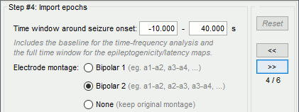
Time window: Select 10s before and 40s after the onset.
Electrode montage: Bipolar 2
Click on [>>] to import the epochs and apply the bipolar montage.
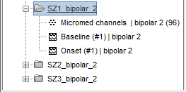
Step 5: Time-frequency
This step computes the time-frequency decomposition of the SEEG signals around the seizure onset and normalizes them based on the same measure computed from the baseline.
For information about the parameters or the display/interpretation of the results, see this section.
At the end of the computation, two figures appear, showing all the time-frequency maps averaged across all the seizures. The first window shows all the contacts individually (click on one contact to display it in a separate window), and the other one represents the average of all the contacts.
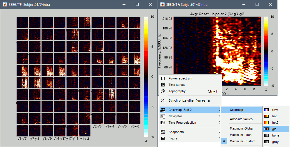
- Use these figures to identify the frequency band of interest for this subject: 120-200Hz
Step 6: Epileptogenicity
Last step of the analysis, it reproduces what is illustrated in this section.
Frequency band: Enter what you visually identified previously (120-200Hz), or select the relevant part of the time-frequency map with your mouse and click on [Get].
Latency list: 0s (no propagation expected, looking only at the first 3 seconds)
Time constant: 3s (duration of the time window used to estimate the epileptogenicity map)
Propagation threshold: p-value threshold on the epileptogenicity map for the computation of the propagation maps (not applicable here, there is no propagation map computed)
Output type: Volume
File selection: Select only SZ1
(leave your mouse over the list for a while to check the corresponding file names)Click on [>>] to start the computation. Expect it to last for a while...

In output you get exactly the same volume as what was illustrated here.
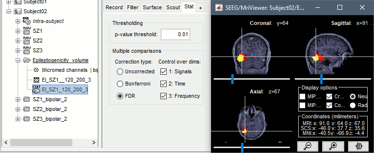
Repeat for SZ2 and SZ3, processed together, on the cortex surface instead of the volume:
Latency list: 0:2:20 s (sliding windows of 3s between 0s and 20s post-seizure)
Output type: Surface
File selection: SZ2 and SZ3
Click on [>>] to start again the computation. There is a lot more to estimate (2 files x 11 epileptogenicity maps), but the computation on the surface is a lot faster.
Same results for Subject01 and Subject02, but on a different surface. The example in the previous section was using the default SPM12 canonical surface, while here we used the modified SPM8 surface including amygdala and hippocampus. Except for this, the two interfaces are equivalent.

Importing realistic surfaces
Instead of using the default SPM canonical surfaces, you can use realistic cortex envelopes, extracted with CAT12, FreeSurfer, BrainSuite or BrainVISA. Instead of importing the anatomy as described previously (pre MRI then post MRI), follow these steps. Note that this cannot be done with the simplified interface in the Guidelines tab.
Right-click on the subject folder > Import anatomy folder:
- Select file type: "BrainVISA folder"
- Select folder: tutorial_epimap/anat/MRI/brainvisa/
- Number of vertices: 15000
When the MRI viewer shows up asking for fiducial points, click on "Click here to compute MNI transformation", then click on [Save] when the computation is done.
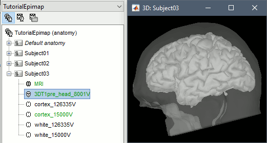
- This is the anatomy of the subject (MRI pre-implantation) processed with the Morphologist pipeline of BrainVISA 4.5. The MRI pre-implantation is now imported, but the post-implantation is still missing.
Right-click on the subject folder > Import MRI:
Import the volume exactly as previously, following these guidelines.
When importing the volumes processed with FreeSurfer, you probably need to register the volume, as FreeSurfer rewrites the volume with a different orientation. Select option [SPM] instead of [Ignore].
In the subject anatomy folder, you can decide to use the pial surface ("cortex") or the grey-white interface ("white") for the computation of the epileptogenicity maps. As these surfaces are fairly different, it may leed to very different results. A SEEG contact close to one surface can be too far from the other to be taken into account in the computation. Make this choice carefully. To change the default surface, right-click > Set as default cortex, or simply double-click on it. Just avoid selecting the high-resolution surfaces (126000 vertices) or the computation will take forever.
Then you can repeat all the steps previously presented. The results may look different depending on the surface you selected (left=cortex, right=white).
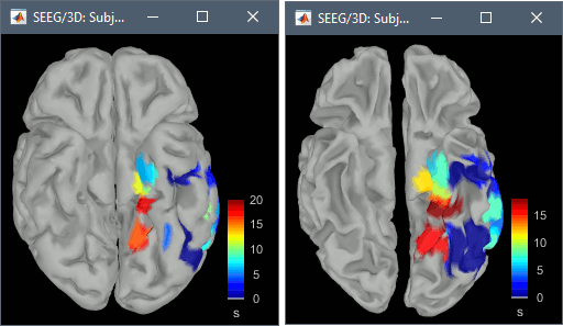
Volume coregistration
When importing two volumes successively in the subject anatomy, you need to coregister all the new volumes with the first volume imported, otherwise you wouldn't be able to do anything with them. The questions that are asked when importing a second volume are the following.
Transformation: This has nothing to do with the coregistration with the first volume, you also got this question when importing the first volume. If you answer "yes" for the first volume, you should probably answer "yes" here as well.
Registration: How to register the new volume with the previous one?
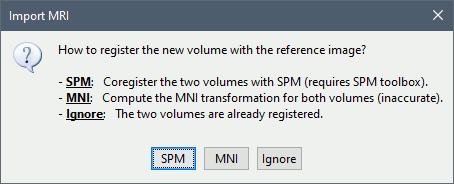
SPM: Uses the SPM toolbox to estimate the rigid transformation from the new volume to the reference volume (the first volume imported). It modifies the voxel=>world transformation in the second volume (vox2ras 4x4 matrix). If you skip this registration step, you can run it later by right-clicking on the second file > Register with default MRI > SPM: Register only.
MNI: Uses SPM code (embedded in Brainstorm) to estimate an affine transformation from each of the two volumes to the MNI normalized space. The transformation from the new volume to the reference is approximated with the two successive MNI transformations: (voxel_new=>MNI) => inv(voxel_ref=>MNI). This gives inaccurate results, and does not guarantee a rigid transformation (there might be slight scaling factor introduced). Do not use this option, unless you have no other option available.
Ignore: Considers that the two volumes are already coregistered. This option will keep the original voxel=>world transformations available in the .nii files, and assume they bring the two volumes in the same space.
Reslice: You have the option to rewrite the new volume so that it matches voxel by voxel the reference volume. If you know that the new file was already registered and resliced before you imported it in Brainstorm, answer NO to this question. Otherwise, this option is necessary if you are expecting to overlay the two volumes in the MRI viewer. If you do not reslice the volume, you would still be able to edit the positions of the SEEG contacts on one or the other volume, but not to superimpose them to check they were registered correctly. This is a limitation of the MRI viewer that will be improved at some point.
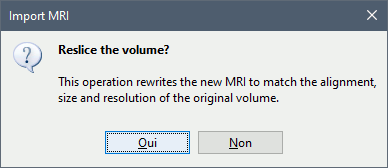
All these options are also available after importing the file. Right-click on the second file > Register with default MRI. The reslice option previously presented corresponds to the menu "Reslice / vox2ras transform". The other reslicing options offer alternatives based on the MNI coordinates or the SCS coordinates, which are most of the time a lot less accurate.
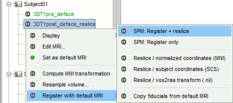
Edit the contacts positions
If you don't have access to the positions of the SEEG contacts in a text file, as illustrated in this tutorial, you can place the contacts in the MRI viewer.
After adding the continuous files to the database, right-click on the channel file > MRI registration > Edit (MRI Viewer: ...). Select one of the post-implantation volumes, that shows clear artifacts around the SEEG contacts.
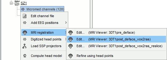
- If the resolution of the pre and post volumes is similar, which is the case in this tutorial, it doesn't matter much if you place the contacts on the resliced or the original post volume. But in the case of a post-implantation CT scan, the resolution is often much higher in the CT. In this case, prefer editing the channel file on the original high-resolution CT rather than on the low-resolution resliced CT volume.
Add the missing information for the electrodes: for positioning the SEEG contacts based on the tip and orientation of the depth electrodes, we need to know the distance between two adjacent contacts on the electrode. In the iEEG tab, select an electrode and fill the field "contact spacing" if it is empty. If the value is the same for all the electrodes, select all the electrodes at once (Ctrl+A) and enter the contact spacing. In the case of these DIXI electrodes, the contact spacing is 3.5mm.
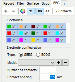
- Then mark all the electrodes one by one:
- In the iEEG tab, select one electrode.
- In the MRI Viewer, place the cursor at the tip of the depth electrode.
In the iEEG tab, click on button [Set tip], the button turns green.
In the MRI Viewer, place the cursor at the entrance of the electrode in the skull, or anywhere else along the depth electrode if this is more convenient. We don't use the actual position of this point, we only use it to estimate the direction of the electrode from its tip. Then click on button [Set skull entry]. The button turns green and the electrode appears in the MRI viewer.
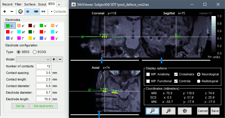
- If there are contacts available for this electrode, this would also place them along the depth electrode. If the positions for these contacts was already defined, you should get a warning asking whether you want to update their positions.
From time to time, you can click on the menu Contacts > Save modifications in the iEEG tab. This would prevent you from losing your work if anything unexpected happens.
When you are done with marking all the electrodes, click on [Save] in the MRI viewer. You can then display the electrodes you placed in 3D (right-click on the channel file > Display sensors).
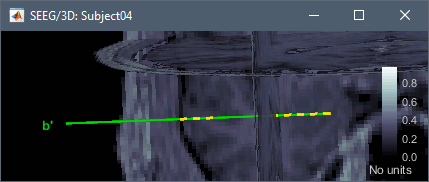
Editing implantation without recordings
You can also start defining an implantation scheme without any recordings in your database. You can use this option for creating a text file with all the contacts positions, and use it in Brainstorm or any other program.
Go back to the subject anatomy, right-click on the appropriate post-implantation volume > SEEG/ECOG implantation.
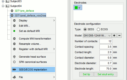
- It creates a new folder "Implantation" in the subject, and starts editing an empty channel file. You need to create the electrodes and set their models (or all their properties) before placing them in the MRI viewer. When you place an electrode, it creates all the corresponding contacts, while in the previous case, it was only setting the position of the existing contacts.
At any moment, you can export the 3D positions of the contacts you created to a text file with the menu Contacts > Export contacts positions in the iEEG tab.
- When you are done, click on [Save] in the MRI viewer. It saves the new channel file and updates the number of channels in the database explorer.
On the hard drive
The definition of the depth electrodes is saved in the channel file, in the field IntraElectrodes. It contains all the information that can be edited in the iEEG tab. The position of the SEEG contacts is saved in the field Channel(i).Loc, as described in the tutorial Channel file. ChannelMat.IntraElectrodes is an array of structures with the following fields.
Name: String identifying the depth electrode in the iEEG tab.
Type: String identifying the type of device, 'SEEG' or 'ECOG'.
Model: String identifying the make and model of the electrode (eg. 'DIXI D08-05AM Microdeep'). This is of known electrode models is accessible with panel_ieeg('GetElectrodeModels').
Loc: [3xN] positions with all the relevant points for the device (tip and entry for SEEG depth electrode, 4 corners for ECOG grid).
Color: [1x3] color vector.
ContactNumber: Number of SEEG/ECOG contacts on this device.
ContactSpacing: Distance between the centers of two contacts in the electrode (meters).
ContactDiameter: Diameter of the yellow cylinders representing the contacts (meters).
ContactLength: Length of the yellow cylinder representing the contacts (meters).
ElecDiameter: Diameter of the cylinder representing the SEEG depth electrode (meters).
ElecLength: Length of the cylinder representing the SEEG depth electrode (meters).
Visible: 0 or 1, indicates in the electrode should be rendered in the figures.
Additional documentation
Related tutorials
Scripting
The following script from the Brainstorm distribution reproduces the analysis presented in this tutorial page: brainstorm3/toolbox/script/tutorial_epileptogenicity.m

