|
Size: 27367
Comment:
|
Size: 27367
Comment:
|
| Deletions are marked like this. | Additions are marked like this. |
| Line 113: | Line 113: |
| * Choose the tip contact in the readjusted 3D isosurface and this should plot a yellow crosshair marker point on the center of the blob and also update the MRI Viewer's crosshair. At the bottom in click '''Set tip''' and the button turns green indicating that the tip has been set. '''This point in 3D is at the centroid of the blob which gives a more accurate location of the contact compared to the same if chosen from the MRI'''.<<BR>><<BR>> {{attachment:34_elec_pop_tip.png||width="500"}} | * Choose the tip contact in the readjusted 3D isosurface and this should plot a yellow crosshair marker point on the center of the blob and also update the MRI Viewer's crosshair. At the bottom in click '''Set tip''' and the button turns green indicating that the tip has been set. '''This point in 3D is at the centroid of the blob which gives a more accurate location of the contact compared to the same if chosen from the MRI'''.<<BR>><<BR>> {{attachment:34_elec_pop_tip.png||width="650"}} |
SEEG Time-Frequency Fingerprint Analysis for Epileptogenic Zone Localization (under construction)
Authors: xxx.
This tutorial introduces some concepts that are specific to the management of intracranial, SEEG recordings in the Brainstorm environment, and explains how to compute maps of epileptogenicity from ictal and interictal recordings. It is based on a clinical case from the McGovern Medical School, University of Texas Health Science Center at Houston, Texas, USA.
Note that the operations used here are not detailed, the goal of this tutorial is not to introduce Brainstorm to new users. For in-depth explanations of the interface and theoretical foundations, please refer to the introduction tutorials.
NOT FOR CLINICAL USE:
The performance characteristics of the methods and software implementation presented in this tutorial have not been certified as medical devices and should be used for research purposes only.
Contents
- Dataset description
- Download and installation
- Import the anatomy
- Electrode labeling and contact localization (WIP)
- Access the recordings
- Display the depth electrodes
- Display SEEG recordings
- Preprocess recordings
- Import epochs of interest
- Modeling interictal spikes using Min-Norm Imaging
- Modeling ictal wave using Min-Norm Imaging
- Modeling ictal onset with Low Voltage Fast Activity (LVFA) using fingerprint analysis (Sensor Space)
- Modeling ictal onset with LVFA using fingerprint analysis (Source Space)
- Modeling ictal onset with repetitive spiking (Sensor and Source Space)
- Appendix
Dataset description
License
This tutorial dataset (EEG, MRI and CT data) remains property of the McGovern Medical School, University of Texas Health Science Center at Houston, Texas, USA. Its use and transfer outside the Brainstorm tutorials, e.g. for research purposes, is prohibited without written consent. For questions, please contact Yash Shashank Vakilna, MS ( Yash.Shashank.Vakilna@uth.tmc.edu ).
Clinical description
The dataset was recorded at the Epilepsy Monitoring Unit at UTHealth Houston. It includes recordings for a patient who was a 25-year-old right-handed woman with drug-resistant epilepsy since age six and a prior right parietal opercular corticectomy at 15 presented with weekly focal aware seizures featuring a left-hand tingling aura and focal impaired awareness seizures with staring and pouting. In the Epilepsy Monitoring Unit (EMU) she had intermittent right parietal slowing and ten habitual seizures arising from C4-P4, and MRI revealed bilateral perisylvian polymicrogyria (PMG), pachygyria, right posterior temporal periventricular nodular heterotopia, and post-surgical changes. MEG localized discharges to the right superior parietal region adjacent to her previous resection, and SEEG implantation mapped two distinct onset patterns: low-voltage fast activity in right superior parietal PMG during focal aware seizures and repetitive spiking in posterior insular PMG during impaired awareness seizures. After multidisciplinary review, she underwent uncomplicated MR-guided laser interstitial thermal therapy targeting the right superior parietal and posterior insular PMG and remained seizure-free at one-year follow-up.
SEEG recordings
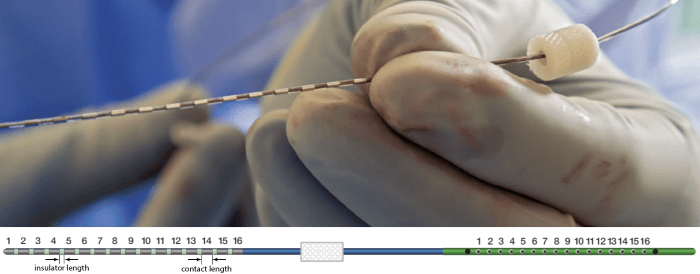
The depth electrodes used in this example dataset are PMT SEEG Depth Electrodes, with the following specifications:
- Diameter: 0.8 mm
- Contact length: 2 mm
- Insulator length: 1.5 mm
- Distance between the center of two contacts: 3.5 mm
- Between 8 and 16 contacts on each electrode
Files
tutorial_seizure_fingerprinting/
anatomy/: Anatomy data
pre_T1.nii.gz: Raw pre-implantation T1 MRI (in NIfTI-1 format)
post_CT.nii.gz: Raw post-implantation CT scan (in NIfTI-1 format)
recordings/: SEEG recordings
Baseline.edf: Raw SEEG recordings (in EDF format) for baseline
ictal_repetitive_spike.edf: Raw SEEG recordings (in EDF format) for seizure with Ictal repetitive spiking
interictal_spike.edf: Raw SEEG recordings (in EDF format) for interictal spike
LVFA_and_wave.edf: Raw SEEG recordings (in EDF format) for seizure onset with Low-voltage-fast-activity
Subject01_electrodes.tsv: Position of contacts localized using Brainstorm. The advanced section Electrode labeling and contact localization explains how it was done.
References
All details for this study can be found here: https://zenodo.org/records/14807262
Download and installation
Requirements: You have already followed all the introduction tutorials and you have a working copy of Brainstorm installed on your computer.
BrainSuite (optional): Make sure you have the latest version of BrainSuite installed. Follow steps as per the BrainSuite for Brainstorm tutorial. This is required to perform skull stripping when importing CT below in order to remove extracranial regions from the CT.
SPM: If you are running Brainstorm from the MATLAB environment, you need to have the SPM12 toolbox installed on your computer, as a Brainstorm plugin or a custom installation.
With the stand-alone compiled version of Brainstorm: all the needed SPM scripts have been compiled and included in the executable. This is required for two purposes:- Coregistration between pre-implantation MRI and post-implantation CT volumes.
Use mask from SPM based tissue segmentation to remove extracranial regions from the CT.
Download the dataset:
Go to the Download page of this website, and download the file: tutorial_seizure_fingerprinting.zip.
- Unzip it in a folder that is not in any of the Brainstorm folders (program folder or database folder).
Brainstorm:
- Start Brainstorm
Select the menu File > Create new protocol. Name it "TutorialSeizureFingerprinting" and select the options:
"No, use individual anatomy",
"No, use one channel file per acquisition run".
Import the anatomy
Pre-implantation MRI
Right-click on the TutorialSeizureFingerprinting folder > New subject > Subject01.
Keep the default options you defined for the protocol.Switch to the Anatomy view of the protocol.
Right-click on the subject node > Import MRI.
Set the file format: MRI: NIfTI-1 (*.nii;*.nii.gz).
Select: tutorial_seizure_fingerprinting/anatomy/pre_T1.nii.gzThe MRI viewer opens automatically. Click on "Click here to compute MNI normalization", option "maff8". This method is embedded in Brainstorm and does not require the installation of SPM12. However, it requires the automatic download of the file SPM12 Tissue Probability Maps. If you do not have access to internet, see the instructions on the Installation page. It is based on an affine co-registration with the MNI ICBM152 template from the SPM software, described in the following article: Ashburner J, Friston KJ, Unified segmentation, NeuroImage 2005..

Click on Save to close the MRI viewer. New node named pre_T1 is created.

While it is not applicable to this data, but while importing some MRIs if there is a transformation available in the NIfTI header, then a window pops up asking Do you would want to apply the transformation to the MRI file ? Choosing Yes will orient the MRI based on this transformation and will reorient the MRI in Brainstorm's standard orientation, so you can see the coronal/sagittal/axial views correctly oriented. More details.
Post-implantation CT
The pre-implantation MRI above will be used as the anatomical reference for this subject. We will now import a second scan done after the SEEG implantation, on which we can see the SEEG contacts. In this dataset, the post-implantation volume is a CT scan (contacts hypersignal appear in white).
Right-click on the subject node > Import CT.
Select: tutorial_seizure_fingerprinting/anatomy/post_CT.nii.gzChoose SPM for coregistration. See the section Volume coregistration for more details on this option.
Choose Yes for reslicing so that the CT voxel dimensions match those of the MRI.

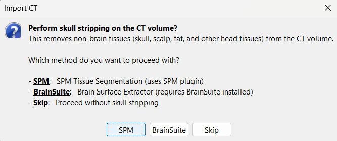
Choose SPM for skull stripping to remove any non-brain tissues as we need just the electrodes inside the brain. See the section Skull Stripping for more details on this option.
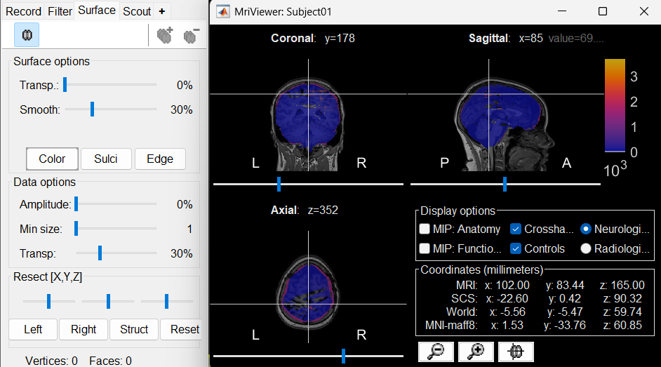
The MRI viewer opens automatically, showing the post-implantation CT volume as a colored layer on top of the previous volume. Adjust the transparency and amplitude threshold of this layer in the section Data options of the Surface tab, adjust its colormap with the popup menu of the figure. Use this display to validate that the coregistration of the two volume is correct, all the parts of the head must align well.
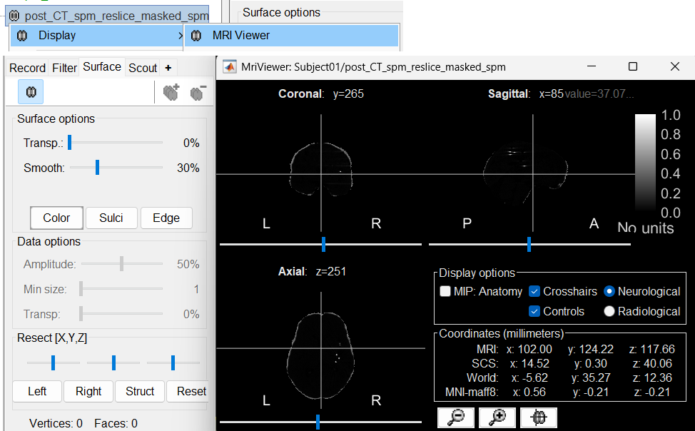
New node named post_CT_spm_reslice_masked_spm is created. The postfix _spm_reslice_masked_spm indicates the different processes it has gone through. To see the history of the processes for this file, right click on post_CT_spm_reslice_masked_spm > File > View file history.

To just view the CT File, right click on post_CT_spm_reslice_masked_spm > Display > MRI Viewer.
Generate default surfaces using CAT12
We recommend generating cortical surfaces with CAT12, especially if you are interested in a realistic representation of the patient's cortical folding in 3D. Follow the CAT12 tutorial to generate the surfaces as under.
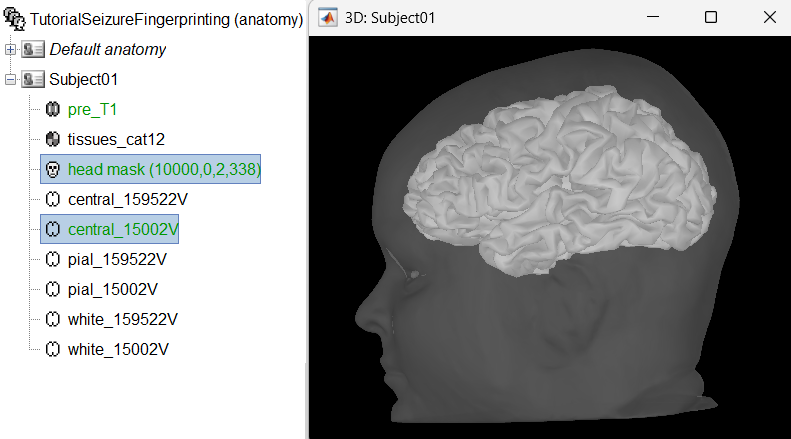
These surfaces will be used later, in the computation of the epileptogenicity maps. Read the section Importing realistic surfaces for information on how to use realistic surfaces from BrainVISA or FreeSurfer.
Electrode labeling and contact localization (WIP)
You can also start defining an implantation scheme without any recordings in your database. You can use this option for creating a text file with all the contacts positions, and use it in Brainstorm or any other program.
Generate isoSurface
This creates a thresholded mesh from the CT by separating the contacts out from rest of the CT. This aids the user towards localization of the electrodes and its contacts more accurately.
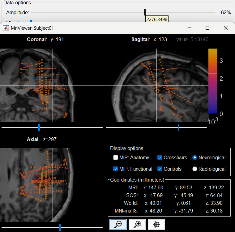
The first thing required is to define a good threshold (which we call isoValue) that will separate out the contacts from the rest of the CT. Just open the CT file (by double clicking on it), click on the MIP: Functional in the MRI Viewer, use the Data Options > Amplitude slider in the Surface tab to browse through the threshold, and once you are satisfied with getting a good separation of the contacts, hover on the slider to get the desired value and keep a note of it (to the nearest integer). In this case the value is 2276.
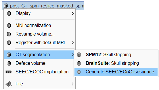
Right click on post_CT_spm_reslice_masked_spm> CT segmentation > Generate SEEG/ECoG isosurface.
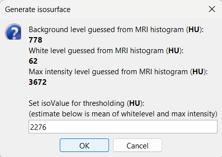
This will bring the Generate isosurface window. This window shows 4 values: the Background level, White level, Max Intensity and the suggested Set isoValue, all of them given in the Hounsfield Unit (HU) scale. The first 3 values are calculated automatically from the histogram of the CT and are displayed for reference. The editable isoValue field shows an estimated best guess based on mean of White Level and Max Intensity. Since we got a better value in step-1 above, set the value to 2276 and press OK.
An isosurface is generated showing the contact as blobs overlayed on the 3D MRI slices. The Thresh slider under Surface options can be further used to fine tune and regenerate mesh with different isoValues.

Start implantation
Right click on Subject01, and choose SEEG/ECOG implantation.
The SEEG/ECOG implantation menu pops to choose which modalities you want to use for doing your implantation with. Choose MRI+CT+IsoSurf. This takes you to the functional tab. Subject01 > Implantation > SEEG/ECOG (0) channel gets created. An MRI Viewer loads up with the CT overlayed on the MRI. A 3D figure loads up with isoSurface and 3D MRI. Panel iEEG loads up in the panel viewer. Move around the 3D slices to get a clear view of the contacts so that they can be clicked on. See the section SEEG/ECOG Implantation Menu for more details on this option.

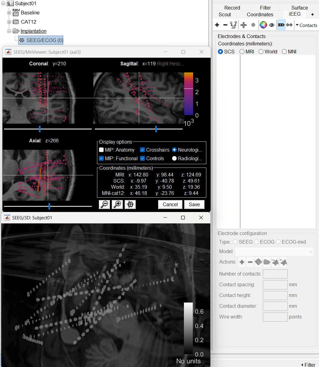
To know more about the panel and its features go to Panel iEEG.
Create electrodes and plot contacts manually
After performing steps above, we will have the Panel iEEG along with the MRI Viewer and 3D figure open. We will be working on the electrode marked below.
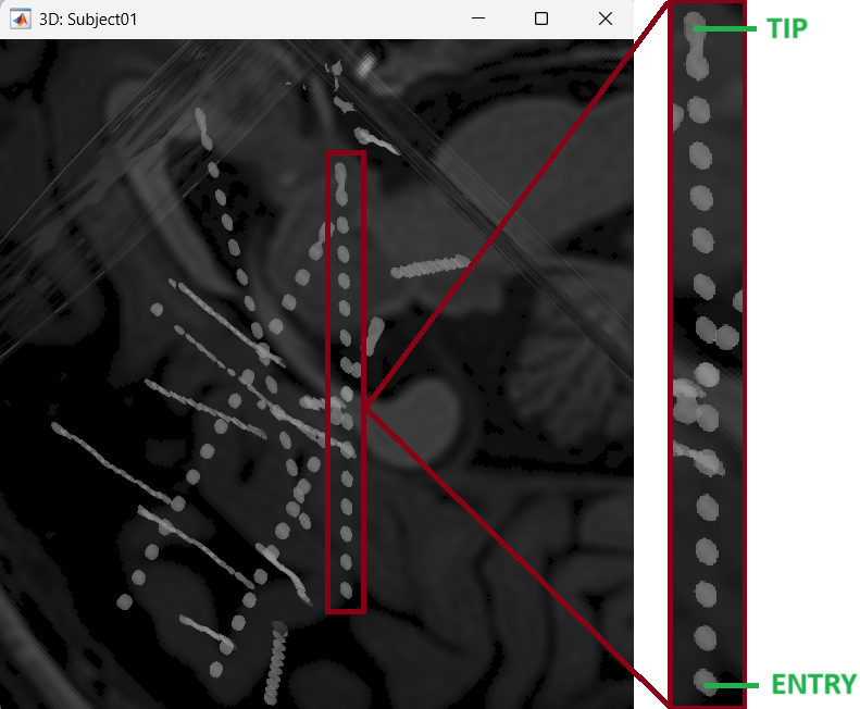
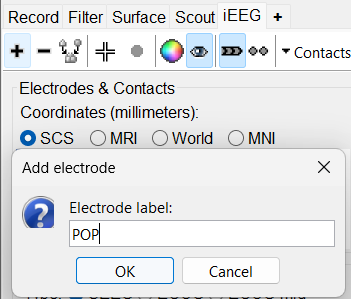
On Panel iEEG Click on the + (Add new electrode). This opens up the Add electrode window. Enter anything under Electrode label based on your convention. For this e.g. enter POP and press OK.
This creates an electrode POP in selected state, and at the bottom the Electrode configuration section of the panel becomes active. Select the following:
Type: SEEG
Model: Choose PMT 2102-16-093/2102-16-103 from the drop down list. This will automatically set the other parameters in the section. More details for these parameters can be found in the advanced section here.
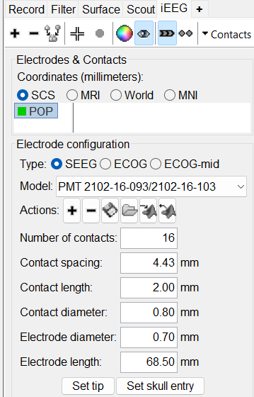
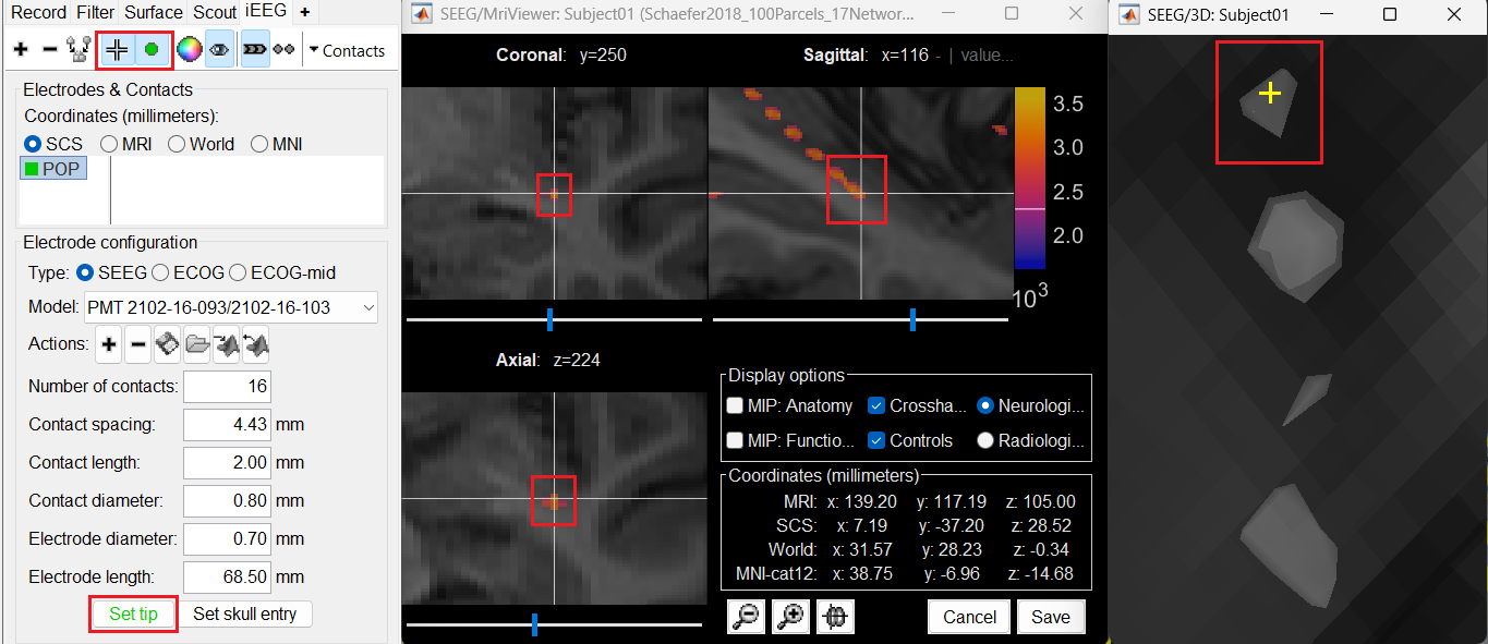
Set tip: Here we set the location of the electrode's contact that is deepest in the brain. As mentioned in here we can set the tip from the MRI Viewer but to get a more accurate location we will leverage the 3D isosurface as described below.
As seen in the first figure in this section, the tip contact blob is not well separated form its following contact. As mentioned in the Generate Isosurface section, switch to Surface tab, use the Thresh slider to adjust the isovalue to approximately 3100 and the will generate a readjusted isosurface that separates out the tip area contacts.
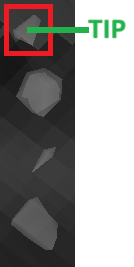
Switch back to the iEEG tab, click the
 button (shortcut: Ctrl+P) to activate surface point selection mode.
 Click on the
 button to activate selecting centroid of the candidate contact blob in the isosurface.
 Choose the tip contact in the readjusted 3D isosurface and this should plot a yellow crosshair marker point on the center of the blob and also update the MRI Viewer's crosshair. At the bottom in click Set tip and the button turns green indicating that the tip has been set. This point in 3D is at the centroid of the blob which gives a more accurate location of the contact compared to the same if chosen from the MRI.
Access the recordings
Link the recordings
- Switch to the "functional data" view (2nd button, on top of the database explorer).
Right-click on the subject folder > Review raw file:
Select the file format: EEG: EDF/EDF+
Select all the recordings: tutorial_seizure_fingerprinting/recordings/*.edf
The new files Link to raw file let you access directly the contents of the original SEEG files. The menu Review raw file does not actually copy any data to the database. More details.

Import the contacts positions
In order to generate epileptogenicity maps, we need accurate 3D positions for the contacts of the depth electrodes. Placing the contacts requires a good understanding of the implantation scheme reported by the neurosurgeon, and some skills in reading MRI scans. To make this tutorial easier to reproduce and follow, we distribute the positions of the contacts (that were localized as per the section above) saved in a text file.
- The channel file "EDF channels" contain the name of the channels, but not their positions. We need to import or edit separately the positions of the SEEG contacts.
Click on the [+] next to the four folders, select all the channel files simultaneously.
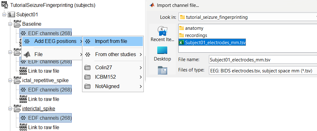
Right-click one channel file > Add EEG positions > Import from file
Select format: EEG: BIDS electrodes.tsv, subject space mm (*.tsv)
Select file: tutorial_seizure_fingerprinting/Subject01_electrodes.tsv
Select a scaling factor: 1
The positions in this text file are in millimeters, the expected unit for this file format is also millimeters, there is no adjustment to make here.

For the reference MRI, since the Subject01_electrodes.tsv file consists of contact positions which were localized on the post_CT after it was coregistered to the pre_T1, resliced and skull-stripped within Brainstorm, so selecting either of them as the reference MRI would be fine as they are both in the same space. Since we localized the contacts from post_CT , select post_CT_spm_reslice_masked_spm.
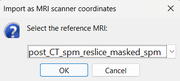
At the end, you get a report indicating how many channels from the SEEG recordings were attributed a new 3D position. The channels are matched by name: the position file you import must include the labels of the channels and they must be named exactly in the the same way as in your recordings.
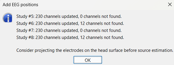
For EDF Channels under LVFA_and_wave and interictal_spike, there were 12 channels not found. The type of the channels for which a position was not found is set to EEG_NO_LOC, in order to ignore them when processing the SEEG data. In this example dataset, the channels numbered 245 to 255 and 262 are not found as they are not SEEG contacts.
You should always validate that the type of all the channels has been detected correctly. Check also that the names are correct and using the same convention for all the contact of a given electrode. These are entered manually, and typing errors are frequent. Right-click on a channel file > Edit channel file.

To edit one channel, double-click on the text to modify. To edit multiple channels, select them all and right-click > Set channel group/type. The column Group corresponds to the name of the depth electrode. It is detected based on the channel type and name. If you include as SEEG a channel that detected as something else or rename a channel, you would need to manually update the channel name.
If you don't have the positions for the SEEG contacts, or if they don't look correctly aligned, you can directly place them in the MRI viewer. See the section Edit the contacts positions.
Display the depth electrodes
3D figures
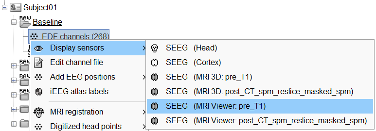
Right-click on the channel file > Display sensors and explore all the available options.
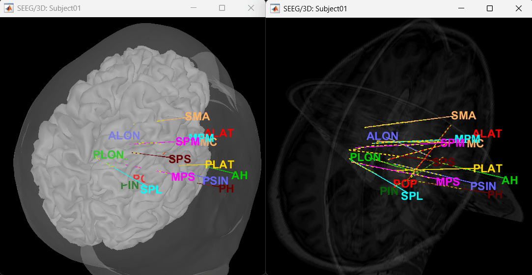
You can render the SEEG depth electrodes in 3D together with the subject anatomy: surfaces, pre- or post-implantation volumes. You can add more anatomy elements to the figure with the button Add a surface (
 ) at the top-right of the Surface tab. For more help: Display the anatomy.
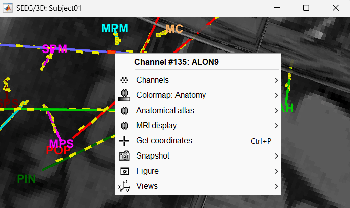
Click on a contact to select it, right-click on it to get its name.
MRI Viewer
You can also display the contacts in the MRI viewer, on top of the the pre- or post-implantation volumes. By default, the electrode is displayed in a slice if there is a SEEG contact associated to it in the slice.
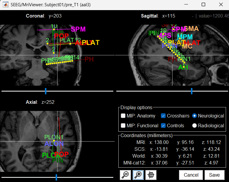
To display all the electrodes, select the option "MIP: Functional". For a glass-brain view, select at the same time the option "MIP: Anatomy".
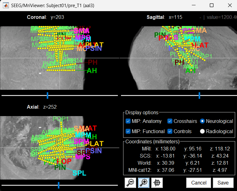
Zoom in/out with the buttons or the associated shortcuts (Ctrl+Scroll or +/-) and explore the volume with (Shift+)x/y/z. Additional display options are available in the popup menu for this figure. All the shortcuts are listed in this tutorial.
You can edit the position of a contact directly clicking on its dot in one of the slice and moving it around. To do it you need to open the MRI Viewer in Edit mode by right clicking on the channel file > MRI registration > Edit ... (MRI Viewer:...). Modifications are not saved immediately and can be cancelled when you close the window. Alternatively, you can right-click on the figure > Set electrode position.

Panel iEEG
When opening SEEG/ECOG recordings, the panel iEEG is added to the Brainstorm window. You can use it to edit the display properties of the depth electrodes. In this interface, "electrode" refers to entire depth electrode implanted in the head of the patient while "contact" refers to recording sites on the electrode. There are multiple contacts on an electrode, and one contact corresponds to one channel of data in the channel file and the recordings.
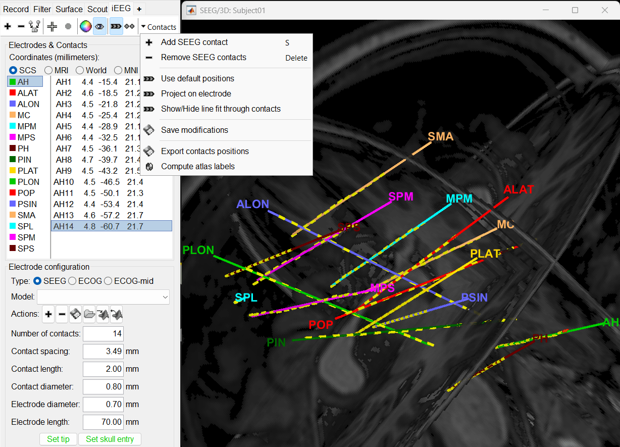
More details about the iEEG Panel can be found here.
Display SEEG recordings
SEEG time series
Briefly introduce about SEEG time series and then point to ReviewRaw tutorial for more about how to use the viewer.
Preprocess recordings
Talk briefly about removing power line noise and marking bad channels for this data. Point to tutorials Power spectrum and frequency filters and EEG and Epilepsy.
Import epochs of interest
- Import recordings into database for further analysis
- Bipolar montage
Modeling interictal spikes using Min-Norm Imaging
Modeling ictal wave using Min-Norm Imaging
Modeling ictal onset with Low Voltage Fast Activity (LVFA) using fingerprint analysis (Sensor Space)
Modeling ictal onset with LVFA using fingerprint analysis (Source Space)
Modeling ictal onset with repetitive spiking (Sensor and Source Space)
Appendix
SEEG/ECOG Implantation Menu
While starting manual implantation on an volume by right click on subject node > SEEG/ECOG implantation, the menu below pops up allowing the user to choose which modality or modalities to proceed with.

MRI: MRI viewer loads up with MRI volume only.
CT: MRI viewer loads up with CT volume only.
MRI+CT: MRI viewer loads up with the CT overlayed on the MRI.
MRI+CT+IsoSurf: MRI viewer loads up with the CT overlayed on the MRI. 3D figure loads up with the IsoSurface and 3D MRI slices.
Cancel: Abort the process.
Skull Stripping
Skull stripping is done on the MRI volume to get a binary volumetric mask of just the brain region. On applying this mask to volumes like CT, it helps in removing any non-brain tissues like skull, scalp, fat, and any other head tissues from the CT volume. In this tutorial, we have a CT scan of a subject with intracranial electrodes, so on applying this mask not only removes the non-brain tissues but also the hanging extracranial wires. Brainstorm has the following menu options for skull stripping:

SPM: Uses SPM toolbox's Tissue Segmentation.
BrainSuite: Uses BrainSuite's Brain Surface Extractor.
Skip: Proceed without skull stripping.

