|
Size: 9057
Comment:
|
Size: 23472
Comment:
|
| Deletions are marked like this. | Additions are marked like this. |
| Line 1: | Line 1: |
| = Tutorial 13: Head model = ''Authors: Francois Tadel, John C Mosher, Richard Leahy, Sylvain Baillet'' |
= Tutorial 20: Head modeling = ''Authors: Francois Tadel, Elizabeth Bock, John C Mosher, Richard Leahy, Sylvain Baillet'' |
| Line 4: | Line 4: |
| This tutorial is still based on Sabine Meunier's somatotopy experiment, called ''TutorialCTF ''in your Brainstorm database. The recordings have already been imported and analyzed at the sensors level, they are ready for source estimation. | The following tutorials describe how cerebral currents can be estimated from the MEG/EEG recordings we have processed so far. To achieve this, we need to consider two distinct modeling problems: the modeling of the electromagnetic properties of the head and of the sensor array (a.k.a. '''head model''' or '''forward model'''), and the estimation of the brain sources which produced the data, according to the head model in question. That second step is known as '''source modeling''' or solving an '''inverse problem'''. It requires that forward modeling of head tissues and sensor characteristics is completed first. This tutorial explains how to compute a head model for the participant to the auditory oddball experiment.'' '' |
| Line 6: | Line 6: |
| <<TableOfContents(2,2)>> | <<TableOfContents(2,2)>> '' '' |
| Line 8: | Line 8: |
| == Forward problem == The first step consists in computing a model that explains how an electric current flowing in the brain can influence what is recorded out of the head, by the EEG or MEG sensors. |
<<TAG(Advanced)>> '' '' |
| Line 11: | Line 10: |
| * This problem is called forward problem. * Its result is called ''head model ''in Brainstorm interface, but can also be referred as ''forward model'' or ''leadfield matrix''. * In the Brainstorm software, we consider by default that the electric or magnetic activity which is recorded by the sensors is produced mainly by a set of electric dipoles located at the surface of the cortex.<<BR>> * The grid of sources (dipoles) that is used is defined by the cortex surface we have imported in one of the previous tutorials; each vertex of this surface is considered as a dipole. * The default surface distributed with Brainstorm have around 15,000 vertices. So we will have 15,000 dipole amplitudes to estimate. Using less vertices would just lower the resolution of the results; using more produces too much data and might lead to memory issues. * What we expect to get at the end of this process is a matrix whose size is [Number of sensors x Number of sources] * For computing this matrix, three methods are available for MEG recordings in Brainstorm: * '''Single sphere''': the head is considered a homogeneous sphere * '''Overlapping spheres''': Refining the previous model by fitting one local sphere for each sensor * '''OpenMEEG BEM''': Symmetric Boundary Element Method from the open-source software OpenMEEG. Described in an advanced tutorial: [[Tutorials/TutBem|BEM head model]]. |
== Why estimate sources? == Reconstructing the activity of the brain from MEG or EEG recordings involves several sophisticated steps. Although Brainstorm simplifies the procedures, it is important to decide whether source modeling is essential to answer the neuroscience question which brought you to collect data in the first place. '' '' |
| Line 22: | Line 13: |
| {{attachment:forwardInverse.gif}} | If one of your primary objectives is to '''identify and map''' the regions of the brain involved in a specific stimulus response or behavior, source estimation can help address this aspect. Empirical interpretations of sensor topographies can inform where brain generators might be located: which hemisphere, what broad aspect of the anatomy (e.g., right vs. left hemisphere, frontal vs. posterior regions). Source estimation improves anatomical resolution further from the interpretation of sensor patterns. The spatial resolution of MEG and EEG depends on source depth, the principal orientation of the neural current flow, and overall SNR: still, a sub-centimeter localization accuracy can be expected in ideal conditions, especially when contrasting source maps between conditions in the same participant. As for other imaging modalities, spatial resolution of group-level effects (i.e. after averaging across multiple participants) is limited by the accuracy of anatomical registration of individual brain structures, which are very variable between participants, and intersubject variations in functional specialization with respect to cortical anatomy. |
| Line 24: | Line 15: |
| == Single sphere model == Select the ''TutorialCTF ''protocol, close all the figures, and follow these steps: |
Source mapping is a form of '''spatial''' '''deconvolution''' of sensor data. In EEG in particular, scalp topographies are very smooth and it is common that contributions from distant brain regions overlap over large clusters of electrodes. Moving to the source space can help discriminating between contributing brain regions. '' '' |
| Line 27: | Line 17: |
| 1. Right-click on the ''Right'' condition and select ''Compute head model''. The ''Head modeler'' window will appear.<<BR>><<BR>> {{attachment:popupHeadModel.gif}} --- {{attachment:headModeler.gif}} 1. Set the options for your head model: * Source space: '''Cortex surface'''. <<BR>>The MRI volume option will be introduced in an advanced tutorial: [[Tutorials/TutVolSource|Volume source estimation]]. * Forward modeling method: '''Single sphere'''. * You can also edit the '''Comment '''field of the file that will be created (the string that will be representing the head model in the database explorer). * Click on ''Run''. |
In '''MEG''', source maps can be a great asset to alleviate some issues that are specific to the modality. Indeed in MEG and contrarily to EEG, the head of the participant is not fixed with respect to sensor locations. Hence data sensor topographies depend on the position of the subject's head inside the MEG sensor array. Therefore, between two runs of acquisition, or between subjects with different head shapes and sizes and positions under the helmet, '''the same''' '''MEG sensors may pick up signals from different parts of the brain'''. This problem does not exist in EEG, where electrodes are attached to the head and arranged according to standard positions. '' '' |
| Line 34: | Line 19: |
| 1. Two other windows appear, to help you define the sphere. Estimating the best fitting sphere for a head is not always as easy as it looks like, because a human head is usually not spherical. <<BR>><<BR>> {{attachment:helpBfs.gif|editBfs.gif}} <<BR>><<BR>> {{attachment:editBfsFigure.gif}} * Read and follow the instructions in the help window. * Click on the ''Scalp ''button, move and resize the sphere manually, just to see how it works. * Click again on ''Scalp'': here we will use directly the estimation of the sphere based on the vertices of the ''Scalp ''surface (a simple least-squares fitting using all the vertices of the surface). * For EEG 3-shell spheres models, you just estimate and manipulate the largest sphere (scalp), and then use the ''Edit properties...'' button in the toolbar to define the relative radii of the 2 other spheres, and their respective conductivities. This will be described in another tutorial. * Click on ''Ok'', and wait for a few seconds. |
Another important point to consider when interpreting MEG sensor maps and that can be solved by working in the MEG source space instead, is that MEG manufacturers use different types of sensor technology (e.g., magnetometers vs. gradiometers; axial vs. tangential gradiometers, etc. yielding different physical measures). This is not an issue with EEG, with essentially one sensor type (electrodes, dry or active, all measuring Volts). |
| Line 41: | Line 21: |
| 1. A new file appeared just below the channel file, it represents the head model.<<BR>><<BR>> {{attachment:headModelPopup.gif}} * There is not much you can do with this file, as it is only a matrix that converts the cortical sources into MEG/EEG recordings, and we do not have any sources information yet. * You may just check the sphere(s) that were used to compute the head model. |
Nevertheless, if your neuroscience question can be solved by measuring signal latencies over broad regions, or other aspects which do not depend crucially on anatomical localization (such as global signal properties integrated over all or clusters of sensors), source modeling is not required. To sort out this question will influence the time and computational resources required for data analysis (source analysis multiplies the needs in terms of disk storage, RAM and CPU performance). |
| Line 45: | Line 23: |
| == Overlapping spheres model == Let's compute a more advanced forward model. The overlapping spheres method is based on the estimation of a different sphere for each sensor. Instead of using only one sphere for the whole head, it estimates a sphere that fits locally the shape of the head in the surroundings of each sensor. |
<<TAG(Advanced)>> '' '' |
| Line 48: | Line 25: |
| 1. Right-click on ''Right'' condition and select ''Compute head model'' again. 1. Select the ''Overlapping spheres'' method and click on ''Run''. 1. This algorithm is supposed to use the inner skull surface from the subject, but we usually do not have this information. In this case, a pseudo-innerskull is reconstructed using a dilated version of the cortex envelope. 1. Right-click on the new head model > ''Check spheres''. This window shows the spheres that were estimated. You can check them by following the indications written in green at the bottom of the window: use left/right arrows. At each step, the current sensor marker is displayed in red, and the sphere you see is its local estimation of the head shape. 1. Close this window when you reviewed them all.<<BR>><<BR>> {{attachment:osTree.gif}} {{attachment:checkSpheres.gif}} 1. Compute a head model for the Left condition (Overlapping spheres). |
== The origins of MEG/EEG signals == To better understand how forward and inverse modeling work, we need to have a basic understanding of the physiological origins of MEG/EEG signals. Note that, as always with modeling, we need to deal with various degrees of approximation. '' '' |
| Line 55: | Line 28: |
| == Selection of a head model == We now have two head models in for our ''Subject01 / Right'' condition. |
Overall, it is assumed that most of - but not exclusively - the MEG/EEG signals are generated by postsynaptic activity of ensembles of cortical pyramidal neurons of the cerebral cortex. The reason is essentially in the morphology and mass effect of these cells, which present '''elongated shapes, '''and are''' grouped in large assemblies of cells ''''''oriented''' '''in a similar manner approximately normal to the cortex'''. Mass effects of close-to-simultaneous changes in post-synaptic potentials across the cell group add up in time and space. These effects can conveniently be modeled at a mesoscopic spatial scale with electric dipoles distributed along the cortical mantle (green arrows in figure below). Note that there is growing evidence that MEG and EEG are '''also sensitive to deeper, cortical and subcortical structures''', including brain nuclei and the cerebellum. Brainstorm features advanced models of these structures, as an option to your analysis. The emphasis in this tutorial is on cortical source models, for simplicity. |
| Line 58: | Line 30: |
| * You can have several head models computed for the same dataset, but it is not recommended as it might be difficult afterwards to know which one was used to compute the sources. * If you want to keep them anyway, you have to indicate which one is the default one. You do that by double-clicking on one of them (or right-click > set as default head model), and it is supposed to turn green. The head model displayed in green is the one that will be used for the following computation steps. * For MEG, when it works properly, the overlapping spheres model usually gives better results than the single sphere one. In this particular case, it produces more focal results, so we are going to use it for the next steps. * For EEG, always prefer the "OpenMEEG BEM" model. * Now to make things clearer: delete the'' Single sphere'' head model, and keep the ''Overlapping spheres''. |
The primary and volume currents generated by current dipoles create differences in electrical potentials and magnetic fields that can be detected outside the head. They can be measured with electrodes placed on the skin (EEG, with respect to a reference) or very sensitive magnetic detectors (MEG). '' '' |
| Line 64: | Line 32: |
| == Batching head model computation == You can run in two clicks the computation of the overlapping spheres model for all the conditions or subjects you want in the database. |
. {{attachment:origins.gif||width="538",height="342"}} '' '' . <<HTML(<div align="right"><FONT size="-1" color="#CCCCCC"><I>Matti Hamalainen, 2007</I></FONT></div>)>> '' '' |
| Line 67: | Line 35: |
| * The ''Compute head model'' menu is available in popup menus in the tree at all the levels (protocol, subject, condition). It is then applied recursively to all the subjects and conditions contained in the node(s) you selected. * Example: If you want to compute it on all the subjects and all the conditions, select the ''Compute head model'' menu from the protocol node ''TutorialCtf''. For all the conditions of ''Subject01'', run it from the ''Subject01 ''popup menu. Etc. * If you only want to compute it on some subjects of the protocol, select them at once holding the ''Ctrl ''key, right-click on one, and select the ''Compute head model ''menu''.'' * To process all the subjects for one condition, switch to the ''Functional data (sorted by conditions)'' view of the database. |
<<TAG(Advanced)>> '' '' |
| Line 72: | Line 37: |
| == Additional discussions on the forum == * Sensor modeling: http://neuroimage.usc.edu/forums/showthread.php?1295 * Gain matrix: http://neuroimage.usc.edu/forums/showthread.php?918 * EEG reference: http://neuroimage.usc.edu/forums/showthread.php?1525#post6718 * EEG and default anatomy: http://neuroimage.usc.edu/forums/showthread.php?1774 |
== Source models == ==== Dipole fitting vs distributed models ==== MEG/EEG source estimation consists in modeling brain activity with current dipoles. A current dipole is a convenient model equivalent to the net post-synaptic electrophysiological activity of local assemblies of neurons. Two main approaches have been explored for source MEG/EEG estimation: '''dipole fitting methods''' - where the position and amplitude of one to a few equivalent current dipoles (ECD) are estimated over relatively short time windows - and '''distributed models''' - where the location (and typically, the orientation) of a large number dipoles is fixed; the dipoles sample a spatial grid covering the entire brain volume or the cortical surface - requiring estimation of the amplitude of a vast number of dipoles in a fixed grid at each time point. '' '' |
| Line 78: | Line 41: |
| = From continuous tutorials: = == Source analysis == Let's reproduce the same observations at the source level. The concepts related with the source estimation are not discussed here; for more information, refer to the introduction tutorials #6 to #8. |
Equivalent dipole fitting approaches are quite straightforward and can be adequate when the number of brain regions expected to be active is small (ideally only one). Therefore, it is most adequate for responses at early post-stimulus latencies. They cannot generalize to capture complex dynamics over extended period of time (epochs) and the associated estimation techniques are quite sensitive to initial conditions (how many dipoles to fit? where does the search start? etc). Our strategy in Brainstorm is to promote distributed source models, which are less user dependent, can generalize to all experimental conditions, and yield time-resolved image volumes that can be processed in many different, powerful ways (group statistics, spatial segmentation, use of regions of interest, correspondence with fMRI, etc.) |
| Line 82: | Line 43: |
| First, '''delete''' all the files related with the source estimation calculated in the previous tutorials, available in the ''(Common files)'' folder: the head model, the noise covariance and inverse model. We can now provide a better estimate of the noise (affects the inverse model), and we defined new SSP operators (affects the head model). | ==== Source constraints ==== |
| Line 84: | Line 45: |
| === Head model === Right-click on any node that contains the channel file (including the channel file itself), and select: "'''Compute head model'''". Leave all the default options: cortex source space, and overlapping spheres. The lead field matrix is saved in file "Overlapping spheres" in ''(Common files)''. |
When opting for distributed source models, the '''positions and orientations of the elementary dipoles''' that will define the "voxel" grid of the source images produced need to be defined. This set of dipoles is called the '''source space'''. By default, Brainstorm constrains the source space to the '''cortex''', where signal-to-noise and sensitivity is maximum in MEG/EEG. Note however that more complete models that include subcortical structures and the cerebellum are available in Brainstorm. Therefore, one decision you need to make before proceeding with source imaging is whether more complete source spaces are required to answer your neuroscience question. |
| Line 87: | Line 47: |
| {{http://neuroimage.usc.edu/brainstorm/Tutorials/TutRawAvg?action=AttachFile&do=get&target=forward.gif|forward.gif|class="attachment"}} | For this tutorial, we use the simple approach where current dipoles are automatically assigned to each of the vertices of the cortical surface (see the nodes in the grey mesh in the leftmost image below). When importing the anatomy of the subject, we downsampled the cortex surface to '''15,000 vertices'''. |
| Line 89: | Line 49: |
| <<EmbedContent("http://neuroimage.usc.edu/bst/get_prevnext.php?prev=Tutorials/ExploreRecordings&next=Tutorials/NoiseCovariance")>> | This default number of 15,000 vertices is empirical. In our experience, this balances the adequate geometrical sampling of cortical folds with the volume of data to be analyzed. To use a smaller number of vertices (sources) oversimplifies the shape of the brain; to use more vertices yields considerably larger data volumes, without necessarily adding to spatial resolution, and may lead to practical hurdles (CPU and memory issues.) |
| Line 91: | Line 51: |
| <<EmbedContent(http://neuroimage.usc.edu/bst/get_feedback.php?Tutorials/HeadModel)>> | ==== Orientation constraints ==== After defining the locations of the dipoles, we also need to define their '''orientations'''. Brainstorm features two main options: unconstrained dipole orientations or orientations constrained perpendicularly with respect to the cortical surface. In the '''unconstrained '''case, '''three orthogonal dipoles '''are assigned to each vertex of the cortex surface. This triplet can account mathematically for local currents flowing in arbitrary directions. The total number of elementary sources used in that case amounts to '''45,000 dipoles''' (3 orientations x 15,000 vertices). In the '''constrained''' case, '''one dipole''' is assigned to each vertex with its orientation perpendicular to the cortical''' '''surface. The benefit to this option is that it restricts the number of dipoles used to '''15,000''' (one per vertex). Results are also easier to process and visualize. However, there are some instances where such constraint is exaggerated and may bias source estimation, for instance when the individual anatomy is not available for the participant. In the Brainstorm workflow, this orientation constraint is offered as an option of the inverse model and will be discussed in the following tutorial sections. In the present tutorial, we compute the forward model corresponding to a grid of 15,000 cortical sources without orientation constraints (hence a total of 45,000 dipoles). Note that the orientation constraint can be applied subsequently in the workflow: We do not have to take such hard decision (constrained vs. unconstrained source orientation) at this stage. '' '' ==== Whole-brain model ==== The constraint of restricting source locations to the cortical surface can be seen as too restrictive in some cases, especially if subcortical areas and cerebellum are regions of interest to the study. Brainstorm features the possibility to use the '''entire brain volume''' as source space (see green dots below: they represent dipole locations sampling the entire brain volume). One minor drawback of such model is that the results produced are impractical to review. We encourage users interested in more sophisticated approaches to add non-cortical structures to their MEG/EEG model to consult the sections concerning Volume and Mixed Head Volumes in the advanced tutorials about source modeling. '' '' . {{attachment:source_space.gif||width="243",height="200"}} {{attachment:source_volume.gif||width="255",height="200"}} '' '' <<TAG(Advanced)>> '' '' == Forward model == We now need to obtain a model that explains how neural electric currents (the source space) produce magnetic fields and differences in electrical potentials at external sensors (the sensor space), given the different head tissues (essentially white and grey matter, cerebrospinal fluid (CSF), skull bone and skin). '' '' * The process of modeling how data values can be obtained outside of the head with MEG/EEG from electrical current dipoles in the brain is called forward modeling or solving a '''forward problem'''. '' '' * In Brainstorm, we call the outcome of this modeling step a "'''head model'''", a.k.a. '''forward model''', '''leadfield matrix''' or '''gain matrix '''in the MEG/EEG literature. '' '' * In this tutorial we will use the default source space: a lower-resolution cortical surface representation, with 15,000 vertices, serving as location support to 45,000 dipoles (see above: models with unconstrained orientation). Note that we use the terms '''dipole''' and '''source '''interchangeably. '' '' * We will obtain a matrix '''[Nsensors x Nsources] '''that relates the activity of the 45,000 sources to the sensor data collected during the experiment. <<BR>><<BR>> {{attachment:forward_inverse.gif}} '' '' ==== Available methods for MEG forward modeling ==== * '''Single sphere''': The head geometry is simplified as a single sphere, with homogeneous electromagnetic properties. '' '' * '''Overlapping spheres''': Refines the previous model by fitting one local sphere under each sensor. '' '' * '''OpenMEEG BEM''': Symmetric Boundary Element Method from the open-source software OpenMEEG. Described in an advanced tutorial: [[Tutorials/TutBem|BEM head model]]. '' '' * '''DUNEuro FEM''': Finite Element Method from the open-source software DUNEuro. Described in an advanced tutorial: [[https://neuroimage.usc.edu/brainstorm/Tutorials/Duneuro|FEM head model]] ==== Models recommended for each modality ==== * '''MEG''': Overlapping spheres.<<BR>>Magnetic fields are less sensitive to heterogeneity of tissue in the brain, skull and scalp than are the scalp potentials measured in EEG. We have found that this locally fittedspheres approach (one per sensor) achieves reasonable accuracy relative to more complex BEM-based methods: [Leahy 1998], [Huang 1999]. '' '' * '''EEG''': OpenMEEG BEM.<<BR>>Since EEG measures differential electric potentials on the scalp surface it depends on the effects of volume conduction (or secondary currents) to produce the signals we measure. As a result EEG is very sensitive to variations in conductivity not only in the tissue near the brain's current sources but also with the skull and scalp. Some tissues are very conductive (brain, CSF, skin), some are less (skull). A realistic head model is advised for integrating their properties correctly. When computing a BEM model is not an option, for instance if OpenMEEG crashes for unknown reasons, then Berg's three-layer sphere can be an acceptable option. '' '' * '''sEEG/ECoG''': The OpenMEEG BEM option is the only model available for this data modality. '' '' == Computation == The forward models depend on the anatomy of the subject and characteristics of EEG/MEG sensors: the related contextual menus are accessible by right-clicking over channel files in the Brainstorm data tree. '' '' * In the imported '''Run#01''', right-click on the channel file or the folder > '''Compute head model'''. <<BR>>Keep the default options selected: Source space='''Cortex''', Forward model='''Overlapping spheres'''.<<BR>><<BR>> {{attachment:compute_popup.gif||width="254",height="161"}} {{attachment:compute_options.gif||width="211",height="247"}} '' '' * A new file will then appear in the database. Headmodel files are saved in the same folder as the channel file's.<<BR>>This file is required for EEG/MEG source estimation: This next step will be described in details in the following tutorial sections. '' '' * Right-click on the head model file > ''Check spheres''. This window shows the spheres that were estimated to compute the head model. You can visualize and verify their location by following the indications written in green at the bottom of the window: use left/right arrows. At each step, the current sensor marker is displayed in red, and the sphere shown is the local estimation of the shape of the inner skull immediately below the sensor. <<BR>><<BR>> {{attachment:headmodel_popup.gif||width="258",height="124"}} {{attachment:headmodel_spheres.gif||width="272",height="181"}} '' '' * Although in principle, the overlapping-sphere method requires the inner skull surface, this data is not always available for every participant. If not available, a pseudo-innerskull surface is estimated by Brainstorm using a dilated version of the cortex envelope. '' '' Repeat the same operation for the other file. We now have two different acquisition runs with two different relative positions of the head and of the sensors. We now need to compute two different head models (one per head/sensor location set). '' '' * In the imported '''Run#02''', right-click on the channel file > '''Compute head model'''. <<BR>><<BR>> {{attachment:run02_popup.gif||width="265",height="220"}} {{attachment:run02_files.gif||width="193",height="220"}} '' '' <<TAG(Advanced)>> '' '' == Database explorer == This section contains additional considerations about the management of the head model files. '' '' * If '''multiple head models '''were computed in the same folder (e.g., after experimenting different forward models), one will be displayed in green and the others in black. The model in green is selected as the default head model: it will be used for all the following computation steps (e.g., source estimation). To change the default to another available head model, double-click on another head model file (or right-click over that file > Set as default head model). '' '' * You can use the database explorer for '''batching the computation''' of head models (across runs, subjects, etc.). The "Compute head model" item is available in contextual menus at multiple instances and all levels of the database explorer. The same forward model type is obtained recursively, visiting all the folders contained in the selected node(s) of the database explorer. '' '' <<TAG(Advanced)>> '' '' == On the hard drive == Right-click on any head model entry > File > View file contents: '' '' . {{attachment:headmodel_contents.gif||width="486",height="440"}} '' '' ==== Structure of the head model files: headmodel_*.mat ==== * '''MEGMethod''': Type of forward model used for MEG sensors ('os_meg', 'meg_sphere', 'openmeeg' or empty). '' '' * '''EEGMethod''':''' '''Type of forward model used for EEG sensors ('eeg_3sphereberg', 'openmeeg' or empty). * '''ECOGMethod: '''Type of forward model used for ECoG sensors ('openmeeg' or empty). * '''SEEGMethod: '''Type of forward model used for sEEG sensors ('openmeeg' or empty). * '''Gain''': Leadfield matrix, [Nsensors x Nsources] (in practice, equivalent to [Nsensors x 3*Nvertices]). * '''Comment''': String displayed in the database explorer to represent this file. '' '' * '''HeadModelType''': Type of source space used for this head model ('surface', 'volume', 'mixed'). '' '' * '''GridLoc''': [Nvertices x 3], (x,y,z) positions of the grid of source points. In the case of a surface head model, it corresponds to a copy of the 'Vertices' matrix from the cortex surface file. '' '' * '''GridOrient''': [Nvertices x 3], directions of the normal to the surface for each vertex point (copy of the 'VertNormals' matrix of the cortex surface). Empty in the case of a volume head model. '' '' * '''GridAtlas''': In the case of mixed head models, contains a copy of the "Source model options" atlas structure that was used for creating the model. '' '' * '''SurfaceFile''': Relative path to the cortex surface file related with this head model. '' '' * '''Param''': In case of a surface head model, it contains a description of the sphere that was estimated for each sensor (Center/Radius).<<BR>> '' '' * '''History''': Date and brief description of the method used for computing the head model. '''Gain matrix''' '' '' The Gain matrix is the most important piece of information in the structure. It stores the leadfields for 3 orthogonal orientations (x,y,z) at each grid point (p1, p2, etc). The information relative to each pair sensor <-> grid source point is stored as successive columns of the matrix are ordered as: ['''p1'''_x, '''p1'''_y, '''p1'''_z, p2_x, p2_y, p2_z ...]. For the tutorial introduction dataset, with 15002 sources, the gain matrix has 45006 columns. To convert this unconstrained leadfield matrix to that of an '''orientation-constrained model''', where the orientation of each dipole is fixed and normal to the cortex surface: '' '' * Export the head model file to the HeadModel structure: Right-click > File > '''Export to Matlab'''. '' '' * At the Matlab prompt:<<BR>> > Gain_constrained = '''bst_gain_orient'''(HeadModel.Gain, HeadModel.GridOrient); '' '' * The dimension of the output matrix is three times smaller (now only one source orientation at each location): [Nsensors x Nvertices] '' '' ==== Useful functions ==== * '''in_bst_headmodel'''(HeadModelFile, ApplyOrient, FieldsList): Read contents of the head model file. * '''bst_gain_orient'''(Gain, GridOrient): Apply orientation constraints. == Additional documentation == ==== Articles ==== * Mosher, Leahy RM, Lewis PS<<BR>>[[http://neuroimage.usc.edu/paperspdf/IEEEBME99.pdf|EEG and MEG: Forward solutions for inverse methods]]<<BR>>IEEE Trans Biomedical Eng, 46(3):245-259, Mar 1999 * Leahy RM, Mosher JC, Spencer ME, Huang MX, Lewine JD (1998)<<BR>>[[http://neuroimage.usc.edu/paperspdf/Phantom_Ver2.pdf|A study of dipole localization accuracy for MEG and EEG using a human skull phantom]]<<BR>>Electroencephalography and Clinical Neurophysiology, 107(2):159-73 * Huang MX, Mosher JC, Leahy RM (1999)<<BR>>[[http://neuroimage.usc.edu/paperspdf/PMB99.pdf|A sensor-weighted overlapping-sphere head model and exhaustive head model comparison for MEG]]<<BR>> Phys Med Biol, 44:423-440 '' '' * Gramfort A, Papadopoulo T, Olivi E, Clerc M<<BR>>[[http://www.biomedical-engineering-online.com/content/9/1/45|OpenMEEG: opensource software for quasistatic bioelectromagnetics]]<<BR>>BioMedical Engineering OnLine 45:9, 2010 ==== Tutorials and forum discussions ==== * Tutorial: [[Tutorials/TutBem|BEM with OpenMEEG]] '' '' * Tutorial: [[Tutorials/TutVolSource|Volume source estimation]] '' '' * External documentation: [[http://www.canada-meg-consortium.org/EN/MegBaillet5|Electromagnetic neural source imaging]] * Forum: Sensor modeling: http://neuroimage.usc.edu/forums/showthread.php?1295 '' '' * Forum: EEG reference: http://neuroimage.usc.edu/forums/showthread.php?1525#post6718 '' '' * Forum: EEG and default anatomy: http://neuroimage.usc.edu/forums/showthread.php?1774 '' '' * Forum: Mixed head models indices: http://neuroimage.usc.edu/forums/showthread.php?1878 '' '' * Forum: Gain matrix units for EEG: http://neuroimage.usc.edu/forums/showthread.php?1837 <<HTML(<!-- END-PAGE -->)>> '' '' <<EmbedContent("http://neuroimage.usc.edu/bst/get_prevnext.php?prev=Tutorials/ChannelClusters&next=Tutorials/NoiseCovariance")>> '' '' <<EmbedContent(http://neuroimage.usc.edu/bst/get_feedback.php?Tutorials/HeadModel)>> '' '' |
Tutorial 20: Head modeling
Authors: Francois Tadel, Elizabeth Bock, John C Mosher, Richard Leahy, Sylvain Baillet
The following tutorials describe how cerebral currents can be estimated from the MEG/EEG recordings we have processed so far. To achieve this, we need to consider two distinct modeling problems: the modeling of the electromagnetic properties of the head and of the sensor array (a.k.a. head model or forward model), and the estimation of the brain sources which produced the data, according to the head model in question. That second step is known as source modeling or solving an inverse problem. It requires that forward modeling of head tissues and sensor characteristics is completed first. This tutorial explains how to compute a head model for the participant to the auditory oddball experiment.
Contents
Why estimate sources?
Reconstructing the activity of the brain from MEG or EEG recordings involves several sophisticated steps. Although Brainstorm simplifies the procedures, it is important to decide whether source modeling is essential to answer the neuroscience question which brought you to collect data in the first place.
If one of your primary objectives is to identify and map the regions of the brain involved in a specific stimulus response or behavior, source estimation can help address this aspect. Empirical interpretations of sensor topographies can inform where brain generators might be located: which hemisphere, what broad aspect of the anatomy (e.g., right vs. left hemisphere, frontal vs. posterior regions). Source estimation improves anatomical resolution further from the interpretation of sensor patterns. The spatial resolution of MEG and EEG depends on source depth, the principal orientation of the neural current flow, and overall SNR: still, a sub-centimeter localization accuracy can be expected in ideal conditions, especially when contrasting source maps between conditions in the same participant. As for other imaging modalities, spatial resolution of group-level effects (i.e. after averaging across multiple participants) is limited by the accuracy of anatomical registration of individual brain structures, which are very variable between participants, and intersubject variations in functional specialization with respect to cortical anatomy.
Source mapping is a form of spatial deconvolution of sensor data. In EEG in particular, scalp topographies are very smooth and it is common that contributions from distant brain regions overlap over large clusters of electrodes. Moving to the source space can help discriminating between contributing brain regions.
In MEG, source maps can be a great asset to alleviate some issues that are specific to the modality. Indeed in MEG and contrarily to EEG, the head of the participant is not fixed with respect to sensor locations. Hence data sensor topographies depend on the position of the subject's head inside the MEG sensor array. Therefore, between two runs of acquisition, or between subjects with different head shapes and sizes and positions under the helmet, the same MEG sensors may pick up signals from different parts of the brain. This problem does not exist in EEG, where electrodes are attached to the head and arranged according to standard positions.
Another important point to consider when interpreting MEG sensor maps and that can be solved by working in the MEG source space instead, is that MEG manufacturers use different types of sensor technology (e.g., magnetometers vs. gradiometers; axial vs. tangential gradiometers, etc. yielding different physical measures). This is not an issue with EEG, with essentially one sensor type (electrodes, dry or active, all measuring Volts).
Nevertheless, if your neuroscience question can be solved by measuring signal latencies over broad regions, or other aspects which do not depend crucially on anatomical localization (such as global signal properties integrated over all or clusters of sensors), source modeling is not required. To sort out this question will influence the time and computational resources required for data analysis (source analysis multiplies the needs in terms of disk storage, RAM and CPU performance).
The origins of MEG/EEG signals
To better understand how forward and inverse modeling work, we need to have a basic understanding of the physiological origins of MEG/EEG signals. Note that, as always with modeling, we need to deal with various degrees of approximation.
Overall, it is assumed that most of - but not exclusively - the MEG/EEG signals are generated by postsynaptic activity of ensembles of cortical pyramidal neurons of the cerebral cortex. The reason is essentially in the morphology and mass effect of these cells, which present elongated shapes, and are grouped in large assemblies of cells oriented in a similar manner approximately normal to the cortex. Mass effects of close-to-simultaneous changes in post-synaptic potentials across the cell group add up in time and space. These effects can conveniently be modeled at a mesoscopic spatial scale with electric dipoles distributed along the cortical mantle (green arrows in figure below). Note that there is growing evidence that MEG and EEG are also sensitive to deeper, cortical and subcortical structures, including brain nuclei and the cerebellum. Brainstorm features advanced models of these structures, as an option to your analysis. The emphasis in this tutorial is on cortical source models, for simplicity.
The primary and volume currents generated by current dipoles create differences in electrical potentials and magnetic fields that can be detected outside the head. They can be measured with electrodes placed on the skin (EEG, with respect to a reference) or very sensitive magnetic detectors (MEG).
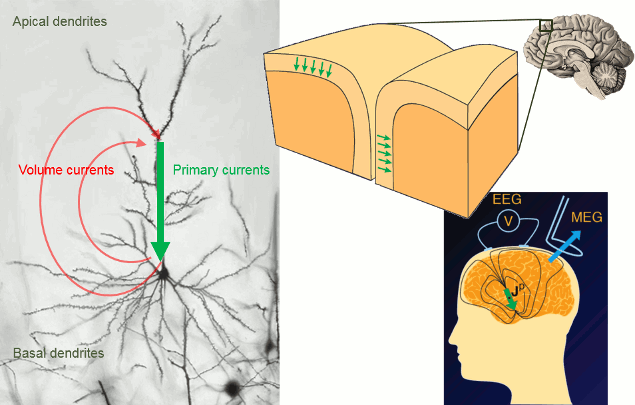
- Matti Hamalainen, 2007
Source models
Dipole fitting vs distributed models
MEG/EEG source estimation consists in modeling brain activity with current dipoles. A current dipole is a convenient model equivalent to the net post-synaptic electrophysiological activity of local assemblies of neurons. Two main approaches have been explored for source MEG/EEG estimation: dipole fitting methods - where the position and amplitude of one to a few equivalent current dipoles (ECD) are estimated over relatively short time windows - and distributed models - where the location (and typically, the orientation) of a large number dipoles is fixed; the dipoles sample a spatial grid covering the entire brain volume or the cortical surface - requiring estimation of the amplitude of a vast number of dipoles in a fixed grid at each time point.
Equivalent dipole fitting approaches are quite straightforward and can be adequate when the number of brain regions expected to be active is small (ideally only one). Therefore, it is most adequate for responses at early post-stimulus latencies. They cannot generalize to capture complex dynamics over extended period of time (epochs) and the associated estimation techniques are quite sensitive to initial conditions (how many dipoles to fit? where does the search start? etc). Our strategy in Brainstorm is to promote distributed source models, which are less user dependent, can generalize to all experimental conditions, and yield time-resolved image volumes that can be processed in many different, powerful ways (group statistics, spatial segmentation, use of regions of interest, correspondence with fMRI, etc.)
Source constraints
When opting for distributed source models, the positions and orientations of the elementary dipoles that will define the "voxel" grid of the source images produced need to be defined. This set of dipoles is called the source space. By default, Brainstorm constrains the source space to the cortex, where signal-to-noise and sensitivity is maximum in MEG/EEG. Note however that more complete models that include subcortical structures and the cerebellum are available in Brainstorm. Therefore, one decision you need to make before proceeding with source imaging is whether more complete source spaces are required to answer your neuroscience question.
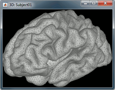
For this tutorial, we use the simple approach where current dipoles are automatically assigned to each of the vertices of the cortical surface (see the nodes in the grey mesh in the leftmost image below). When importing the anatomy of the subject, we downsampled the cortex surface to 15,000 vertices.
This default number of 15,000 vertices is empirical. In our experience, this balances the adequate geometrical sampling of cortical folds with the volume of data to be analyzed. To use a smaller number of vertices (sources) oversimplifies the shape of the brain; to use more vertices yields considerably larger data volumes, without necessarily adding to spatial resolution, and may lead to practical hurdles (CPU and memory issues.)
Orientation constraints
After defining the locations of the dipoles, we also need to define their orientations. Brainstorm features two main options: unconstrained dipole orientations or orientations constrained perpendicularly with respect to the cortical surface.
In the unconstrained case, three orthogonal dipoles are assigned to each vertex of the cortex surface. This triplet can account mathematically for local currents flowing in arbitrary directions. The total number of elementary sources used in that case amounts to 45,000 dipoles (3 orientations x 15,000 vertices).
In the constrained case, one dipole is assigned to each vertex with its orientation perpendicular to the cortical surface. The benefit to this option is that it restricts the number of dipoles used to 15,000 (one per vertex). Results are also easier to process and visualize. However, there are some instances where such constraint is exaggerated and may bias source estimation, for instance when the individual anatomy is not available for the participant.
In the Brainstorm workflow, this orientation constraint is offered as an option of the inverse model and will be discussed in the following tutorial sections. In the present tutorial, we compute the forward model corresponding to a grid of 15,000 cortical sources without orientation constraints (hence a total of 45,000 dipoles). Note that the orientation constraint can be applied subsequently in the workflow: We do not have to take such hard decision (constrained vs. unconstrained source orientation) at this stage.
Whole-brain model
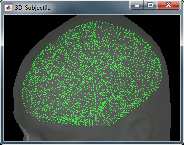
The constraint of restricting source locations to the cortical surface can be seen as too restrictive in some cases, especially if subcortical areas and cerebellum are regions of interest to the study. Brainstorm features the possibility to use the entire brain volume as source space (see green dots below: they represent dipole locations sampling the entire brain volume). One minor drawback of such model is that the results produced are impractical to review. We encourage users interested in more sophisticated approaches to add non-cortical structures to their MEG/EEG model to consult the sections concerning Volume and Mixed Head Volumes in the advanced tutorials about source modeling.
Forward model
We now need to obtain a model that explains how neural electric currents (the source space) produce magnetic fields and differences in electrical potentials at external sensors (the sensor space), given the different head tissues (essentially white and grey matter, cerebrospinal fluid (CSF), skull bone and skin).
The process of modeling how data values can be obtained outside of the head with MEG/EEG from electrical current dipoles in the brain is called forward modeling or solving a forward problem.
In Brainstorm, we call the outcome of this modeling step a "head model", a.k.a. forward model, leadfield matrix or gain matrix in the MEG/EEG literature.
In this tutorial we will use the default source space: a lower-resolution cortical surface representation, with 15,000 vertices, serving as location support to 45,000 dipoles (see above: models with unconstrained orientation). Note that we use the terms dipole and source interchangeably.
We will obtain a matrix [Nsensors x Nsources] that relates the activity of the 45,000 sources to the sensor data collected during the experiment.

Available methods for MEG forward modeling
Single sphere: The head geometry is simplified as a single sphere, with homogeneous electromagnetic properties.
Overlapping spheres: Refines the previous model by fitting one local sphere under each sensor.
OpenMEEG BEM: Symmetric Boundary Element Method from the open-source software OpenMEEG. Described in an advanced tutorial: BEM head model.
DUNEuro FEM: Finite Element Method from the open-source software DUNEuro. Described in an advanced tutorial: FEM head model
Models recommended for each modality
MEG: Overlapping spheres.
Magnetic fields are less sensitive to heterogeneity of tissue in the brain, skull and scalp than are the scalp potentials measured in EEG. We have found that this locally fittedspheres approach (one per sensor) achieves reasonable accuracy relative to more complex BEM-based methods: [Leahy 1998], [Huang 1999].EEG: OpenMEEG BEM.
Since EEG measures differential electric potentials on the scalp surface it depends on the effects of volume conduction (or secondary currents) to produce the signals we measure. As a result EEG is very sensitive to variations in conductivity not only in the tissue near the brain's current sources but also with the skull and scalp. Some tissues are very conductive (brain, CSF, skin), some are less (skull). A realistic head model is advised for integrating their properties correctly. When computing a BEM model is not an option, for instance if OpenMEEG crashes for unknown reasons, then Berg's three-layer sphere can be an acceptable option.sEEG/ECoG: The OpenMEEG BEM option is the only model available for this data modality.
Computation
The forward models depend on the anatomy of the subject and characteristics of EEG/MEG sensors: the related contextual menus are accessible by right-clicking over channel files in the Brainstorm data tree.
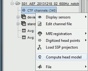
In the imported Run#01, right-click on the channel file or the folder > Compute head model.
Keep the default options selected: Source space=Cortex, Forward model=Overlapping spheres.
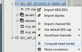
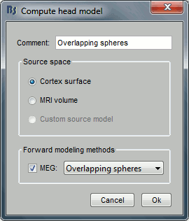
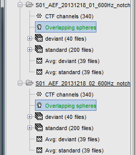
A new file will then appear in the database. Headmodel files are saved in the same folder as the channel file's.
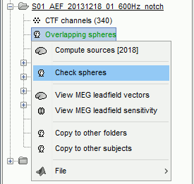
This file is required for EEG/MEG source estimation: This next step will be described in details in the following tutorial sections.Right-click on the head model file > Check spheres. This window shows the spheres that were estimated to compute the head model. You can visualize and verify their location by following the indications written in green at the bottom of the window: use left/right arrows. At each step, the current sensor marker is displayed in red, and the sphere shown is the local estimation of the shape of the inner skull immediately below the sensor.
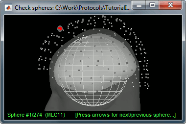
Although in principle, the overlapping-sphere method requires the inner skull surface, this data is not always available for every participant. If not available, a pseudo-innerskull surface is estimated by Brainstorm using a dilated version of the cortex envelope.
Repeat the same operation for the other file. We now have two different acquisition runs with two different relative positions of the head and of the sensors. We now need to compute two different head models (one per head/sensor location set).
In the imported Run#02, right-click on the channel file > Compute head model.
Database explorer
This section contains additional considerations about the management of the head model files.
If multiple head models were computed in the same folder (e.g., after experimenting different forward models), one will be displayed in green and the others in black. The model in green is selected as the default head model: it will be used for all the following computation steps (e.g., source estimation). To change the default to another available head model, double-click on another head model file (or right-click over that file > Set as default head model).
You can use the database explorer for batching the computation of head models (across runs, subjects, etc.). The "Compute head model" item is available in contextual menus at multiple instances and all levels of the database explorer. The same forward model type is obtained recursively, visiting all the folders contained in the selected node(s) of the database explorer.
On the hard drive
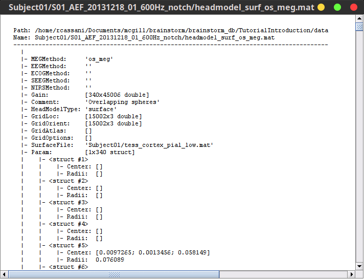
Right-click on any head model entry > File > View file contents:
Structure of the head model files: headmodel_*.mat
MEGMethod: Type of forward model used for MEG sensors ('os_meg', 'meg_sphere', 'openmeeg' or empty).
EEGMethod: Type of forward model used for EEG sensors ('eeg_3sphereberg', 'openmeeg' or empty).
ECOGMethod: Type of forward model used for ECoG sensors ('openmeeg' or empty).
SEEGMethod: Type of forward model used for sEEG sensors ('openmeeg' or empty).
Gain: Leadfield matrix, [Nsensors x Nsources] (in practice, equivalent to [Nsensors x 3*Nvertices]).
Comment: String displayed in the database explorer to represent this file.
HeadModelType: Type of source space used for this head model ('surface', 'volume', 'mixed').
GridLoc: [Nvertices x 3], (x,y,z) positions of the grid of source points. In the case of a surface head model, it corresponds to a copy of the 'Vertices' matrix from the cortex surface file.
GridOrient: [Nvertices x 3], directions of the normal to the surface for each vertex point (copy of the 'VertNormals' matrix of the cortex surface). Empty in the case of a volume head model.
GridAtlas: In the case of mixed head models, contains a copy of the "Source model options" atlas structure that was used for creating the model.
SurfaceFile: Relative path to the cortex surface file related with this head model.
Param: In case of a surface head model, it contains a description of the sphere that was estimated for each sensor (Center/Radius).
History: Date and brief description of the method used for computing the head model.
Gain matrix
The Gain matrix is the most important piece of information in the structure. It stores the leadfields for 3 orthogonal orientations (x,y,z) at each grid point (p1, p2, etc). The information relative to each pair sensor <-> grid source point is stored as successive columns of the matrix are ordered as: [p1_x, p1_y, p1_z, p2_x, p2_y, p2_z ...]. For the tutorial introduction dataset, with 15002 sources, the gain matrix has 45006 columns.
To convert this unconstrained leadfield matrix to that of an orientation-constrained model, where the orientation of each dipole is fixed and normal to the cortex surface:
Export the head model file to the HeadModel structure: Right-click > File > Export to Matlab.
At the Matlab prompt:
> Gain_constrained = bst_gain_orient(HeadModel.Gain, HeadModel.GridOrient);The dimension of the output matrix is three times smaller (now only one source orientation at each location): [Nsensors x Nvertices]
Useful functions
in_bst_headmodel(HeadModelFile, ApplyOrient, FieldsList): Read contents of the head model file.
bst_gain_orient(Gain, GridOrient): Apply orientation constraints.
Additional documentation
Articles
Mosher, Leahy RM, Lewis PS
EEG and MEG: Forward solutions for inverse methods
IEEE Trans Biomedical Eng, 46(3):245-259, Mar 1999Leahy RM, Mosher JC, Spencer ME, Huang MX, Lewine JD (1998)
A study of dipole localization accuracy for MEG and EEG using a human skull phantom
Electroencephalography and Clinical Neurophysiology, 107(2):159-73Huang MX, Mosher JC, Leahy RM (1999)
A sensor-weighted overlapping-sphere head model and exhaustive head model comparison for MEG
Phys Med Biol, 44:423-440Gramfort A, Papadopoulo T, Olivi E, Clerc M
OpenMEEG: opensource software for quasistatic bioelectromagnetics
BioMedical Engineering OnLine 45:9, 2010
Tutorials and forum discussions
Tutorial: BEM with OpenMEEG
Tutorial: Volume source estimation
External documentation: Electromagnetic neural source imaging
Forum: Sensor modeling: http://neuroimage.usc.edu/forums/showthread.php?1295
Forum: EEG reference: http://neuroimage.usc.edu/forums/showthread.php?1525#post6718
Forum: EEG and default anatomy: http://neuroimage.usc.edu/forums/showthread.php?1774
Forum: Mixed head models indices: http://neuroimage.usc.edu/forums/showthread.php?1878
Forum: Gain matrix units for EEG: http://neuroimage.usc.edu/forums/showthread.php?1837

